 Languages
Kneading Block Selection: Stagger Angle, Disc Width and Disc Count
-
-
Kneading Block Selection: Stagger Angle, Disc Width and Disc Count
Three numbers on an element drawing decide whether a block disperses, distributes, or simply builds pressure.
KNEADING BLOCK · TWIN SCREW EXTRUDER ELEMENTS · STAGGER ANGLE · DISPERSIVE MIXING
-
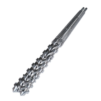
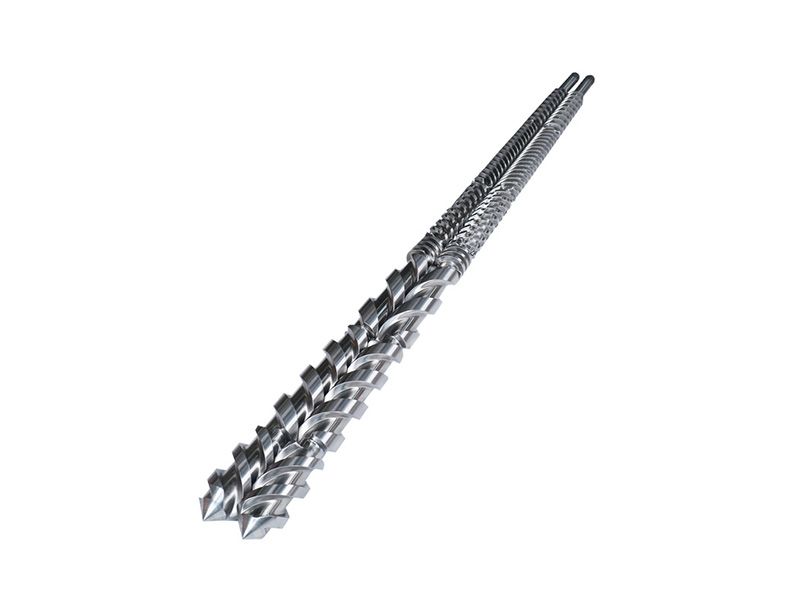
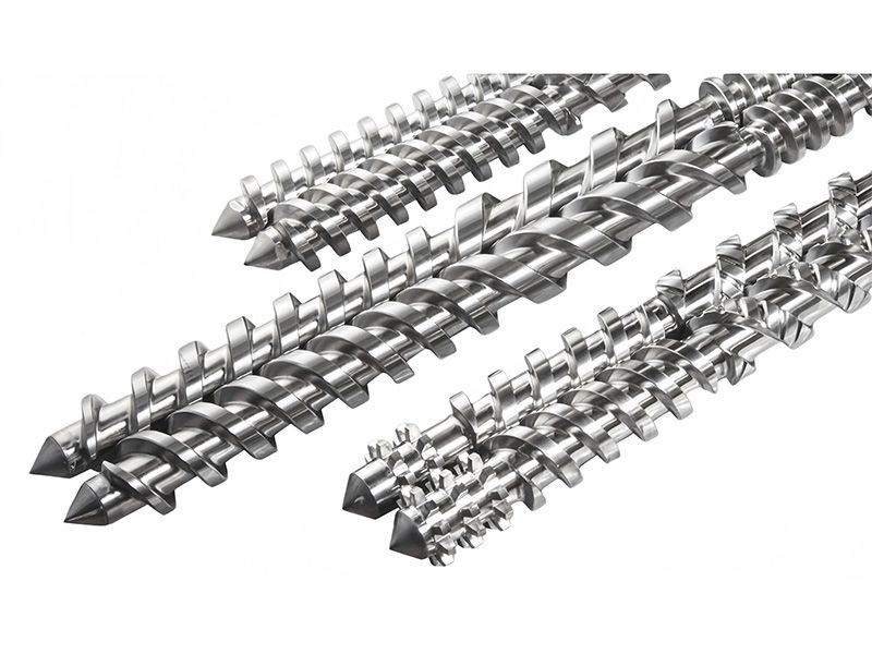
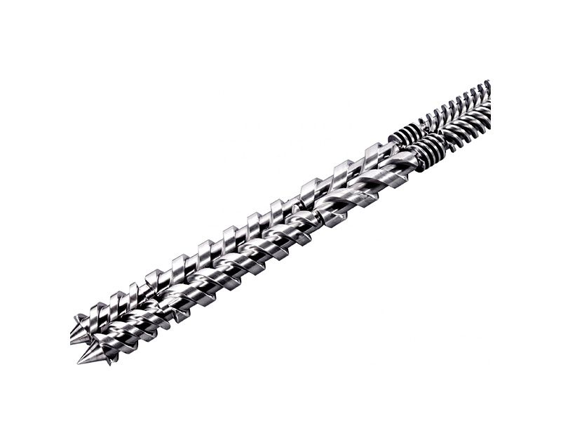
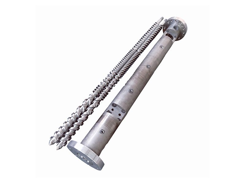
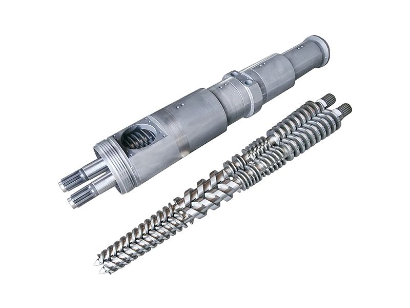
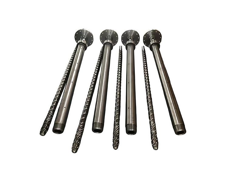
A modular twin-screw pair. The elements are stacked on a splined shaft, so the same barrel can run a gentle distributive configuration or an aggressive dispersive one — the difference is entirely in what is stacked where.
-
1. What a kneading block actually does
A conveying element moves material forward with minimal work. A kneading block does the opposite: it deliberately interrupts forward flow so the polymer is folded, sheared and recombined. Everything a compounding line achieves in terms of dispersion, distribution and pressure build happens in a small number of these blocks, which is why the geometry matters more than the tonnage of steel.
On a parallel twin the block is a stack of elliptical discs on a splined shaft. Three things define it: the offset angle between adjacent discs, the width of each disc, and how many discs are stacked. Change any one and you have a different element that behaves differently in the same barrel.
KEY INSIGHT
A kneading block is a mixing decision expressed as a part number. If the part number changes without the mixing requirement changing, someone has guessed.What a block costs is more than its price. It consumes shaft length that could have been conveying length, adds torque the drive has to deliver, and holds material at temperature longer than the flights on either side of it. Those three costs are why a configuration is designed rather than assembled from the most aggressive parts available — the residence-time arithmetic puts numbers to the third, and the compounding configuration notes show how the first two are traded in practice.
Element work is usually discussed as a twin-screw subject, and it is, but the same mixing logic shows up elsewhere. A barrier section on a single screw is doing distributive work with a different geometry, and a conical twin reaches the same melt state with a different shaft. The twin screw overview and the application index are where those routes are compared.
-
A modular twin screw pair. The elements are stacked on a splined shaft, so the same barrel can run a gentle distributive configuration or an aggressive dispersive one — the difference is entirely in what is stacked where.
-
2. Stagger angle: the choice that sets the character
The offset angle between discs is the first thing to fix, because it decides whether the block pushes material forward, holds it in place, or pushes it back. The four standard angles are not a quality ladder — they are four different tools.
Angle Mixing character Forward conveying Where it belongs 30° Gentle distributive blending, low shear Best of the four — close to a conveying element Heat-sensitive compounds, early melting, gentle homogenisation 45° Balanced dispersion and distribution Reduced but still positive General colour and filler masterbatch, PE and PP modification 60° Strong dispersive mixing, breaks agglomerates Poor — relies on upstream pressure Glass-fibre wetting, high CaCO3 loading, carbon black 90° Maximum shear, no forward component None — neutral Devolatilisation, reactive extrusion, high-viscosity blending Two practical consequences follow. First, a 60° or 90° block is a restriction: the upstream elements have to be able to fill it, or output falls and the melt overheats in the wrong place. Second, a stack of high-angle blocks raises torque more than the pressure gauge suggests — which is why a configuration that looks reasonable on paper can trip a drive on start-up.
Torque is the check that decides whether a configuration is buildable at all. Adding a second 60° stack is the standard route to more dispersion and also the standard reason a drive trips on a cold start, because both the restriction and the start-up viscosity peak arrive together. If the machine is already near its torque ceiling, the answer is usually a longer mixing section at a lower angle rather than more of both.
The angle also maps to the compound more directly than most selection tables admit. Heat-sensitive work such as rigid PVC wants the gentlest stack that will still homogenise; polyolefins such as PE and PP tolerate far more; and engineering grades like polyamide sit in between, with a narrow melting window that punishes a badly placed high-angle block.
-
3. Handedness: right, left and neutral
Direction is separate from angle, and it is the part of a block drawing that gets misread most often. Discs stacked clockwise convey forward; discs stacked counter-clockwise convey backward and are used deliberately to build back pressure or to seal a zone. A neutral stack conveys neither.
- A left-hand block is a design feature, not a mistake — it creates the fill and pressure a downstream operation needs
- A left-hand block in the wrong place starves everything after it
- Neutral and left-hand blocks are where residence time and degradation risk concentrate
This is also why an element that looks visually similar to another supplier's can behave differently. The spline, the hand and the angle all have to match before two blocks are interchangeable, and the replacement details worth confirming apply to elements as much as to barrels.
Interchangeability is narrower than the catalogue implies. Matching the outside diameter and the lobe count is not enough; two blocks are only equivalent when the spline and the overall length also match. That is why a brand-compatible element has to be quoted against a shaft drawing, and why the twin screw replacement details start with the interfaces rather than the dimensions.
-
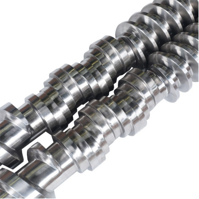
Kneading discs stacked to a specific width and offset. The width is a mixing specification, not a manufacturing convenience — a substitute width changes the dispersion the line actually achieves.
-
4. Disc width: narrow distributes, wide disperses
Width is where most specifications stop being specific. A narrow disc forces material to split and rejoin repeatedly as it passes each disc edge, which is distributive mixing. A wide disc drags a longer surface past the barrel wall and generates a higher local shear stress, which is dispersive mixing.
Disc width Flow behaviour Mixing type Watch for Narrow Frequent stream splitting, lower local stress Distributive — good for colour and minor components May not break agglomerates at all; looks mixed but is not dispersed Wide Longer shear surface, higher instantaneous stress Dispersive — good for fillers and fibres Heat build-up and torque peaks; harder on heat-sensitive grades Mixed stack Widths alternate along the block Balances both, at the cost of predictability Harder to document — insist on the disc-by-disc drawing Distribution and dispersion look similar in a sample and are not the same thing. Distribution evens out where the components are; dispersion breaks the agglomerates down. A narrow-disc stack will make a colour look uniform while leaving filler clusters intact, which shows up later as a strength or surface defect — the same distinction that separates melt stability problems from simple mixing complaints.
Mixing is often confused with the rest of the screw. A barrier screw improves melting without dispersing anything, and a grooved feed section changes conveying efficiency rather than mixing quality. Those decisions interact with element choice, which is why the geometry and lubricant matching note is worth reading before a stack is specified.
-
5. Disc count and block length
More discs means more restriction and more torque for the same angle and width. A five-disc 60° stack is not a longer version of a three-disc 60° stack; it is a harder-working element that will hold more material and heat it further. Block length is normally quoted in L/D units so it can be planned into the shaft, and that is the number to compare when two suppliers quote different stacks.
- Length in L/D is comparable across suppliers; disc count alone is not
- Disc count and width together set the length — quote both
- A longer block at the same angle raises torque, which the drive has to accept
- Element length consumes shaft that could otherwise be conveying length
Length is a budget shared with everything else on the shaft. Every L/D given to a kneading block is L/D taken from conveying capacity, venting length or the metering section, so a configuration is always a set of trades rather than a best-practice list. That is the argument for reviewing the whole screw against the duty before any single element is changed, and for treating an existing barrel length as fixed rather than negotiable.
-
6. Where the block sits decides what it achieves
The same block does different work in different positions. Early in the process section it assists melting; after a side feeder it wets and disperses; before a vent it can seal or starve; at the die end it builds pressure. Configuration is therefore a sequence problem, not a shopping list.
That is the argument for reading the whole screw rather than the block. The element selection guide and the conveying versus kneading comparison cover the sequence, and the side-feeding note explains why the block downstream of a side feeder is usually the most heavily loaded one on the shaft.
-
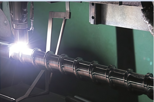
PTA hardfacing being applied to a flight surface. The same deposition logic protects element flanks in abrasive duty, and the finished profile has to be cut after the weld, not before.
-
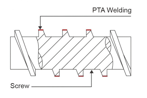
Where a wear layer goes on a flight, and what it does not cover. The root and the flanks carry the load; a coating that only reaches the crest leaves the two surfaces that actually fail unprotected.
-
A typical compounding sequence makes the point better than any description. Conveying elements feed and melt; a moderate-angle block homogenises; a side feeder adds filler or fibre; a high-angle block downstream disperses it; a left-hand or neutral element builds the seal before a vent. Move any one of those blocks and the whole sequence changes, which is why the side-feeding arrangement and the element comparison are read together rather than separately.
The sequence also has to respect what happens after the block. A vent needs a seal in front of it and pressure rebuilt behind it, which is a vented barrel design question before it is an element question. Colour and grade changes are the other constraint: a configuration that holds a lot of material in kneading blocks takes longer to purge, which is the practical argument in the purging and changeover guide .
-
7. What the block is made of
Element metallurgy follows the same logic as the barrel: match the alloy to the damage mechanism, then worry about hardness. A block running 40% glass fibre and a block running rigid PVC are not the same purchase even if the geometry is identical.
Element material Hardness (typical) Best for Trade-off Powder-metallurgy alloy (WR class) HRC 58–65 High-filler, high-shear continuous duty Highest cost; justified only where wear is the limiting factor W6Mo5Cr4V2 high-speed steel HRC 58–62 General compounding, medium shear Good balance; not the answer for aggressive mineral loading Nickel-based alloy Lower, by design Corrosive and flame-retardant compounds Choosing it for abrasion alone is a mis-spec Nitrided 38CrMoAl Case-hardened surface Low-filler, low-shear, cost-sensitive work Case depth is the whole wear budget 316L stainless Not a wear grade Food, medical and pharmaceutical Selected for cleanliness, not life The reasoning is set out at length in the alloy selection guide ; the short version is that bimetallic protection and a harder element solve different problems, and the material selection guide starts from the compound rather than the part.
Material choice follows the damage mechanism, not the price list. A block in glass-filled duty is losing material from the disc flanks; a block in rigid PVC is more likely pitting; a block in food or medical work is chosen for cleanliness before wear. The nitrided baseline covers the economical end of that range, and the through-hardened option sits between it and a coated element.
-
8. How kneading blocks fail
Elements do not usually break; they wear. The flank of each disc loses material until the clearance to the barrel opens, and the visible symptom is a loss of dispersion quality long before anyone measures anything.
- Flank wear: dispersion falls off, gels and agglomerates return
- Root wear under the discs: the block sits lower, clearance grows, shear drops
- Corrosion pitting: roughness traps material and accelerates both
- Spline wear: the element moves on the shaft and the stack no longer holds its timing
The process signals that precede a visible problem are the same ones that diagnose a worn pair — the no-teardown wear check covers them, and the service-life reference gives a rough interval to plan against.
Wear on an element is measurable without removing the shaft, if the machine has an inspection window or a spare barrel. The useful readings are the gap between disc flank and barrel wall at several positions, and the condition of the spline, because a stack that has started to move on its shaft no longer holds the timing the configuration was designed around. Both belong in the same record as the barrel measurements , and the replacement decision is easier to make once they exist.
Wear also decides whether an element can be recovered rather than replaced. A block with flank wear but a sound spline can often be reworked, while one that has lost its seat cannot — the same judgement the repair versus replacement note makes for barrels, applied to a much smaller part. Where a barrel is being salvaged at the same time, a liner sleeve may be the cheaper route than a new bore.
-
9. Reading the element drawing
A usable element drawing states five things, and a quotation that omits any of them cannot be compared with another.
- Offset angle, and the hand (right, left or neutral)
- Disc width and disc count, or total length in L/D
- Spline standard, tooth count and bore size
- Material grade and finished hardness
- Profile after coating, if a wear layer is being applied
Where an existing shaft is being re-elemented rather than replaced, the custom screw route covers the element stack and the shaft together, and the manufacturing note explains what changes when a profile is ground after heat treatment.
The enquiry that gets a usable answer carries the compound, the duty and the existing shaft. Filler type and percentage decide the angle and the alloy; output and screw speed decide how much torque the stack can afford; the shaft drawing decides what will physically fit. The information checklist covers the long version, and the capacity page sets out what lead time that implies.
Where the line runs a single compound and changes nothing, this whole discussion collapses to one question: does the stack match the duty it was bought for? That is a cheaper conversation than re-elementing, and it is the one the single versus twin comparison and the machine selection note set out for buyers who are still choosing the architecture rather than the element.
-
10. The four mis-specifications worth avoiding
Most element problems are bought, not worn. These four recur often enough to be worth checking before an order is placed.
- Buying a harder block for a mixing problem — geometry, not metallurgy, is usually the answer
- Copying an angle without copying the disc width — the pair sets the result
- Adding high-angle blocks to raise dispersion without checking drive torque
- Replacing one element in a worn stack — the new block works against the old ones and the result is unpredictable
The last one is the most expensive. Elements wear as a set because they share a shaft and a clearance, which is the same argument the single versus twin comparison makes about barrels: the working pair is the unit, not the part. For a compounding line being reconfigured for a new compound, the compounding application notes and the four twin architectures are the right starting point, and PIPLL builds elements to a supplied shaft drawing or to a measured one.
For the compound-specific side, the duty decides more than the element: glass-filled and mineral-filled work loads a 60° block hardest, PET and regrind punishes residence time, and WPC and SPC combine filler loading with a thermal window that rules out aggressive stacks.
-
✔ Kneading Block & Twin-Screw Element Specialist | ✔ Stagger Angle · Disc Width · Disc Count · Handedness
✔ Powder-Metallurgy · High-Speed Steel · Nickel Alloy · Nitrided | ✔ Custom Stack · Shaft-Matched · OEM Replacement