A quick calculation and tracer check for heat sensitive compounds — estimate mean residence time from hold-up and throughput, then verify the RTD tail with a repeatable shop-floor tracer test.
A flame-retardant compound keeps turning yellow even after the barrel temperatures are reduced. Torque rises, but occasional dark specks remain. Before making another temperature adjustment, check twin screw residence time alongside actual melt temperature, material preparation and the screw configuration.
The quick calculation divides actual material inventory by stable throughput. This PIPLL guide explains the assumptions, the slow material hidden by the average, and how to follow up with a tracer check and component review.
The Two Minute Twin Screw Residence Time Calculation
For steady operation with a consistent material stream through the section being assessed:
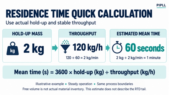
Mean residence time in seconds = 3600 × hold-up mass in kg ÷ throughput in kg/h
For mental arithmetic, convert output to kilograms per minute, then divide hold-up by that rate.
Figure 1 — Convert hourly output to kilograms per minute, then divide the material inventory by that rate.
In the example, 2 kg of hold-up at 120 kg/h gives an estimated mean of 60 seconds. The figures illustrate the arithmetic; they are not measured PIPLL production data.
Quick check: at the same 2 kg inventory, 240 kg/h gives 30 seconds; 60 kg/h gives 120 seconds. The comparison assumes the inventory stays unchanged. In a starve-fed extruder, changing throughput can change hold-up, so recalculate before treating those figures as predictions.
Define the boundaries first. A main-feed-to-die estimate includes solid conveying and melting. A melt-only estimate starts at the chosen melting boundary. Include adapters, screens and the die only if they fall within your selected measurement boundaries.
Estimate the Inventory Before Trusting the Answer
Free volume is the available space around the installed screws, not the amount of plastic actually occupying it. A starve-fed conveying section can be partly filled while a restrictive section is much more fully filled. Leistritz’s engineering approach treats filled and starved sections separately.
For a melt-filled region, or a rough estimate using a justified effective fill fraction:
Hold-up mass in kg ≈ free volume in L × fill fraction × melt density in kg/L
For example, 6 L × 0.40 × 1.1 kg/L = 2.64 kg. At 240 kg/h, the output is 4 kg/min. Therefore, 2.64 ÷ 4 = 0.66 minutes, or approximately 40 seconds.
With the same volume, density and output, fill fractions of 0.25 and 0.55 give about 25 and 54 seconds. These sensitivity examples show why unknown fill calls for an estimated range, rather than an exact time.
Use free-volume data for the installed screws. For mixed solids and melt, estimate inventory section by section with suitable density and fill assumptions. Pellet density does not replace melt density. Without a justified hold-up estimate, the answer remains uncertain.
Read the RTD Curve as Well as the Average
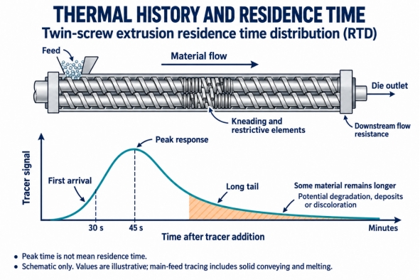
Real material exits over a residence time distribution, or RTD. The average does not mean every particle spends the same time inside. A tracer pulse helps distinguish three observations:
• First arrival: the first detectable tracer at the observation point, within the method’s detection limit.
• Peak response: the time of the strongest measured tracer signal. This is the mode of the response, not automatically the mean.
• Long tail: the remaining response after the peak. Some tracer-marked material leaves much later than the main response.
Figure 2 — A tracer response separates first arrival, peak response and the long tail. Times shown are illustrative.
A long tail can matter for heat-sensitive formulations even when the average looks acceptable. But a visual tail does not quantify a universal final 1–2% of material, and slow washout alone does not prove a severe dead zone. Tracer compatibility, feeder behavior, detection sensitivity and downstream equipment can also affect the result.
Higher Screw Speed Does Not Answer Every RTD Question
PIPLL process note: thermal history depends on the time-temperature path, as well as formulation, moisture, oxygen exposure and mechanical working. Barrel thermocouples remain useful, but they do not directly describe the temperature experienced by every part of the material.
Many co-rotating compounding extruders operate with controlled, starve-fed feeding. At a fixed mass throughput, raising rpm can reduce channel fill and change the balance between conveying, mixing, shear heating and material inventory.
Published Leistritz trials show shorter transit times with higher rpm under their test conditions. They also report that the distribution can broaden. A shorter main response therefore does not establish that every part of the tail has improved. Coperion likewise identifies throughput, element arrangement and downstream restrictions as important RTD variables.
A useful comparison variable is specific feed load. If throughput Q is in kg/h and screw speed N is in revolutions per minute:
Specific feed load in kg/revolution = Q ÷ (60 × N)
At 120 kg/h and 300 rpm, this is about 0.0067 kg/revolution. At the same output and 500 rpm, it is 0.0040 kg/revolution. That change helps explain a different filling condition; it does not calculate residence time by itself.
For PIPLL screw-configuration discussions, record throughput and rpm together with actual melt temperature, torque or power, melt pressure and the full tracer response. Increasing rpm is not a universal cure for yellowing, and a particular torque percentage is not a universal processing limit.
Where Additional Hold Up Can Develop
Restrictive screw elements and kneading blocks
Conveying elements for twin screw extruders and kneading elements perform different duties. Reverse-pitch elements, kneading-block geometry and their placement can change local filling, mixing and pressure generation. Their effect depends on the surrounding arrangement and material behavior; one element does not universally double residence time.
When reviewing twin screw extruder screw elements, consider the complete sequence. Co-rotating screw elements must deliver adequate melting and dispersion as well as acceptable thermal exposure. Removing every restriction may reduce mixing performance. PIPLL asks for the screw layout and operating problem together when discussing component requirements.
Screens and downstream flow resistance
A more restrictive screen pack, adapter or die can change the upstream filled length and inventory. Compare pressure trends before and after screen changes at matched throughput, temperature and rpm. There is no universal 8–10 MPa boundary at which every extruder becomes fully filled.
Side feed and vent transitions
Inspect side-feed interfaces, vent openings and areas where deposits can collect. Vent flooding or char may involve local filling, pressure, vacuum operation, feed changes or deposit buildup. If material is added downstream, it has a different travel history from material entering at the main feed. An outlet tracer test must account for the selected addition point and all streams.
Run a Repeatable Shop Floor Tracer Check
The two-minute calculation is quick; a complete tracer test must continue long enough to observe the tail. It may take several minutes or longer on a particular line.
Prepare a meaningful comparison
Select a plant-approved tracer that is compatible with the formulation, carrier and processing temperature. A contrasting masterbatch may suit a screening trial, but the dose should be small enough not to change flow and large enough to detect. Do not assume that an arbitrary handful or an incompatible pigment will track the resin reliably.
Choose a controlled addition point, use the approved dosing route and define time zero at that boundary. Adding tracer upstream in a feeder also measures feeder delay. Choose a fixed observation point at the die outlet; observing pellets after a water bath or pelletizer adds transport delay. Identify and segregate trial output according to plant quality procedures.
Record the response rather than three guesses
1. Stabilize the line and record formulation, output, rpm, barrel settings, actual melt temperature, pressure and torque or power.
2. Add a brief, documented tracer pulse through the approved feed system. Record the addition duration and start time.
3. Collect sequential samples or video at a fixed interval suited to the expected transit time. Keep lighting, observation point and detection criteria consistent.
4. Record first detection, strongest response and return below a defined detection threshold. Continue sampling long enough to check the late response.
5. Repeat the baseline before changing conditions. Compare one selected process change at a time and wait for a new steady state.
First arrival at 30 seconds, a peak at 45 seconds and visible color at five minutes would justify investigating the spread and possible retention. Those illustrative observations do not establish a 45-second mean or prove the location of a dead zone.
Calculate a measured mean when the signal permits
At constant outlet mass flow, a short tracer pulse and a calibrated concentration signal allow a time-weighted mean:
Measured mean time ≈ sum of (time × tracer concentration × sample interval) ÷ sum of (tracer concentration × sample interval)
Raw camera color intensity is not necessarily proportional to concentration. Calibration, background correction, sufficient tail sampling and tracer recovery matter. If the pulse has appreciable duration, account for its input-time centroid. For changing flow, mass-flow weighting is also needed. Use appropriate RTD analysis when a validated numerical mean is required.
Use the Result to Investigate Yellowing and Dark Specks
If the main response shifts later at lower output, review whether hold-up has decreased in proportion to throughput. If the main response changes little but the late signal grows, check the screw arrangement, interfaces and downstream equipment. If color defects persist without a corresponding tracer change, investigate moisture, oxygen, additive stability, contamination and actual melt temperature as well.
Do not lower every zone temperature automatically. Colder processing can raise viscosity, torque and mechanical work; actual melt temperature may not fall as expected. Work within the material supplier’s and machine maker’s operating guidance, then compare measured quality and process trends.
PIPLL process note: the target is sufficient melting and mixing with controlled thermal exposure. The narrowest possible RTD is not automatically the best process for every compound.
What to Send PIPLL for a Screw and Barrel Review
For a material that yellows, chars or produces recurring specks, send PIPLL the machine model, screw diameter and L/D, element sequence, formulation family, additive or filler content, feed locations, output and rpm. Include actual melt temperature, pressure trends, wear measurements where available and the tracer timeline.
PIPLL’s custom screw and barrel review connects those observations with screw geometry, installation dimensions and material requirements. A request for modular screw elements for compounding should identify the shaft connection, bore geometry, element lengths and rotation system rather than relying only on the machine’s nominal diameter.
The PIPLL plastic compounding twin screw barrel page provides a product starting point; confirm the actual rotation arrangement and dimensions for your machine. For a screw barrel for flame retardant compounds, distinguish potential chemical attack from abrasive wear before discussing PIPLL bimetallic material options . An alloy choice does not correct an unsuitable flow path or excessive thermal exposure.
Discuss the inspection criteria alongside the PIPLL screw and barrel manufacturing process . The useful next step is a documented comparison of the existing setup and the observed problem, not an automatic replacement decision or a promised reduction in residence time.
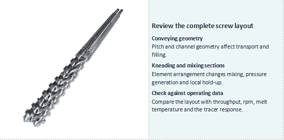
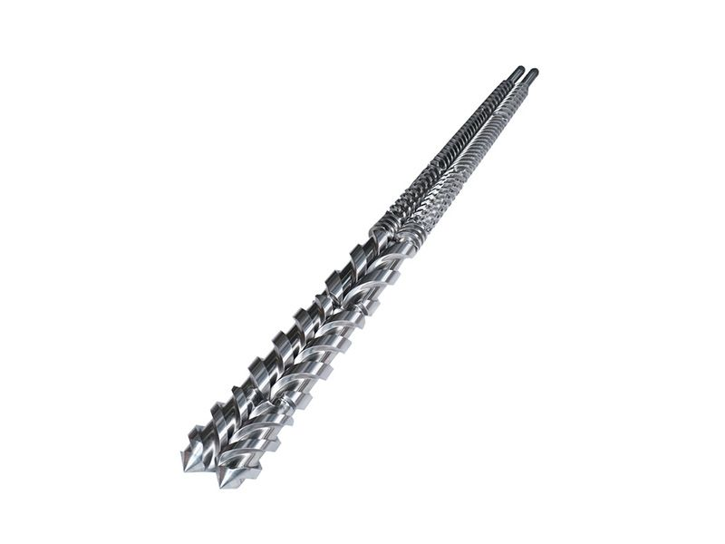
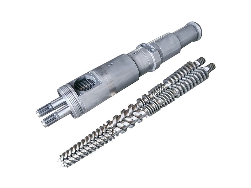
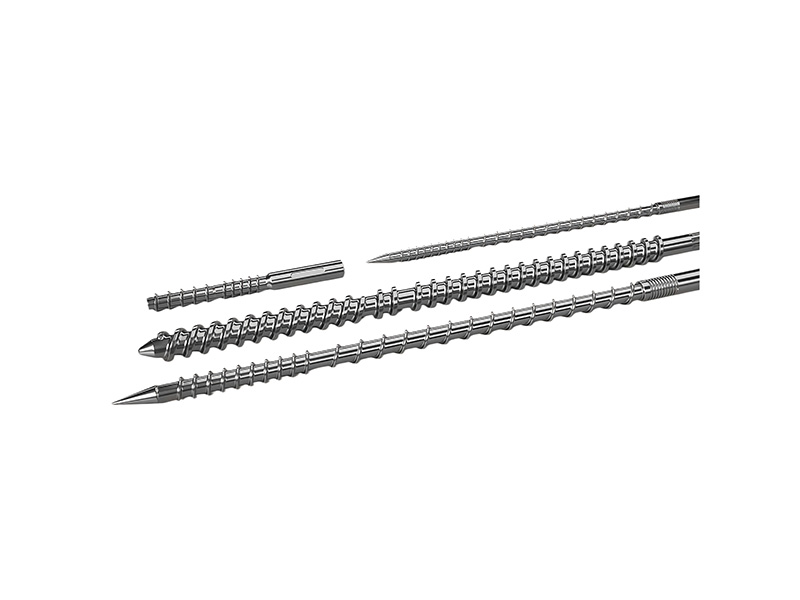
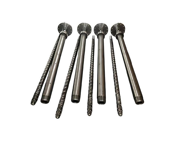
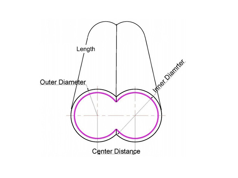
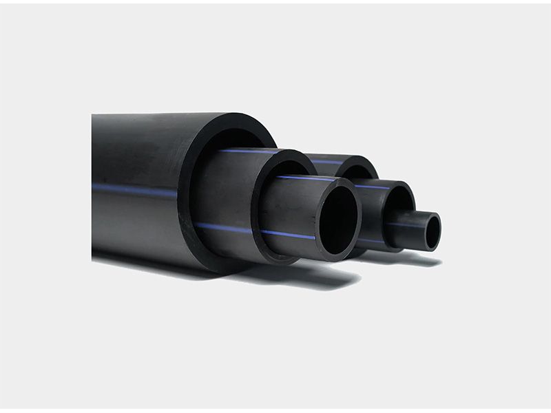
Figure 3 — Product photo from the supplied PIPLL compounding material library. Review the whole layout rather than assigning residence time to one visible section.
Frequently Asked Questions
Can I calculate residence time from screw rpm alone?
No. Rpm does not establish actual inventory, throughput or the RTD. Compare rpm with feed load, screw layout, material behavior and downstream restrictions.
Is the time of darkest color the average residence time?
No. It is an approximate peak-response time. A numerical mean requires a suitable time-weighted tracer signal, with the input pulse and measurement boundaries accounted for.
Can I use the same hold up estimate after changing the screw layout?
Reassess it. Changes in conveying pitch, kneading arrangement or restrictions can alter both free volume and fill. The same caution applies after major throughput or downstream changes.
Will changing the screw and barrel eliminate yellowing?
Only if component condition or geometry contributes to the cause. PIPLL component discussions should also consider formulation, drying, actual melt temperature, operating history and the measured tracer response.
Discuss Your Compounding Problem with PIPLL
Twin screw residence time becomes useful when the estimate and the tracer response describe the same process boundaries. Use the mass-balance calculation for an initial range, then investigate the late response before choosing a process or component change.
Contact PIPLL with your screw layout, resin and additive details, output/rpm pair and tracer observations. Harry can discuss the information needed to assess a suitable screw-and-barrel solution for your equipment.
Harry Jiang | PIPLL
Email: harry@pipll.com | WhatsApp: +86 182 6854 1152
Website: www.pipll.com


+86 15267878906

1306 W building , NB-IoT Industrial Park, No. 199 Changxing Road, Jiangbei, Ningbo.

 Languages