Twin Screw Extruder Screw Elements Selection Guide
Twin screw extruder screw elements should be specified as a sequence, not bought as interchangeable metal pieces. The operating duty of a compounding twin screw barrel determines where conveying, melting, mixing, venting, and pressure building occur. First confirm the machine architecture using this parallel twin screw barrel guide ; then use the installed configuration, material formulation, and production record for a custom screw and barrel review. A co-rotating segmented screw set must not be assumed to fit a counter-rotating or one-piece twin screw simply because the diameter looks similar.
This guide is for compounding-line engineers and buyers preparing a replacement or revised screw configuration. It explains which element data matter, how kneading choices change the process, and what evidence a manufacturer needs before quoting. The central decision is to preserve verified machine interfaces while matching the element sequence to the actual polymer and quality target.
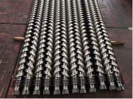
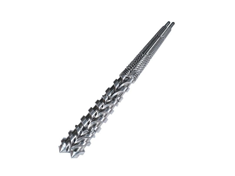
Figure 1. Multiple parallel twin-screw assemblies with different processing profiles. Confirm whether the installed machine uses removable segmented elements before ordering individual parts.
Start With the Correct Twin Screw Architecture
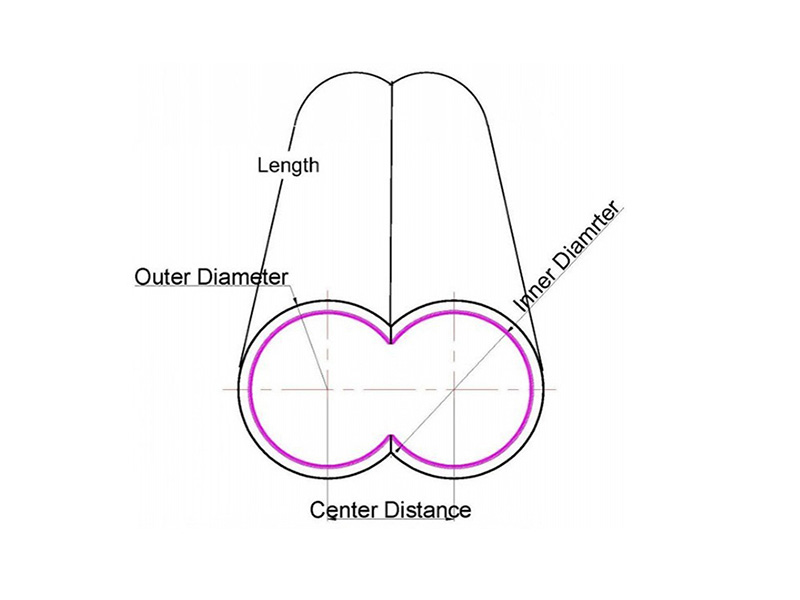
The phrase twin screw extruder screw elements most often refers to modular parts mounted on a shaft in a co-rotating compounding extruder. Other twin-screw machines use different profiles or an integral screw. Rotation direction, intermeshing geometry, center distance, shaft connection, barrel bore, and available process length are therefore identification data, not catalog details.
Request the original screw layout or element list if available. If it is missing, record the extruder make and model, serial number, screw diameter, shaft spline or key form, element length, flight count and direction, barrel configuration, and every measured interface. Brand-compatible parts for a Coperion ZSK, Leistritz, or another machine require drawing-level verification; a brand name alone does not establish fit.
What Each Element Is Asked to Do
| Element family | Main role in the sequence | Specification check |
| Conveying element | Moves solids or melt and helps set local fill and residence time. | Pitch, handedness, flight count, length, and position. |
| Kneading block | Introduces mixing and melting work; its angle and disk arrangement affect conveying and shear. | Staggering angle, disk count, width, direction, and position. |
| Restrictive or reverse element | Raises local fill or pressure when the process calls for it. | Confirm heat history, torque, pressure, and vent interaction. |
| Mixing or specialty element | Addresses a specific dispersion, distribution, or downstream quality need. | Confirm geometry and test objective with the machine supplier. |
An element does not work in isolation. A kneading block can improve mixing while changing conveying, melt temperature, torque, and local filling. A restrictive element placed near a vent can create an unintended process problem. Review the entire sequence with feed points, side feeders, vents, barrel zones, and discharge pressure.
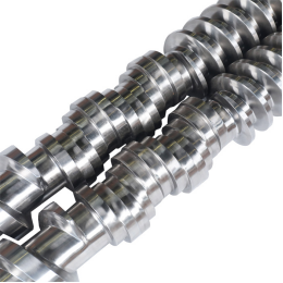
Figure 2. Close view of twin screw mixing geometry. The image shows processing features, not a dimensional specification for modular replacement elements.
How to Compare 30 45 and 60 Degree Kneading Blocks
The 30, 45, and 60 degree kneading block terms in a request refer to disk-staggering geometry. They are not a universal ranking of product quality. In general, angle, disk width, handedness, and downstream elements together influence conveying versus mixing and the amount of mechanical work introduced into the melt. A 45-degree or 60-degree block is not automatically suitable for every resin or filler package.
For a new sequence, state the problem to solve: poor distributive mixing, agglomerates, unmelted particles, unstable venting, excess melt temperature, or unnecessary torque. Compare trial results at the same throughput, screw speed, feed formulation, and temperature profile. If the current line already meets specification, a like-for-like element replacement may be safer than changing the kneading pattern without process evidence.
Match Element Material to Wear and Corrosion Duty
Element steel and surface protection should follow the actual material stream. Glass fiber and mineral fillers increase abrasion; certain additives and processing conditions can add corrosion risk. Clean PP or PE compounding, filled engineering plastics, and recycled compounds should not receive the same material recommendation by default. W6Mo5Cr4V2 and HIP powder-metallurgy options may appear in supplier offers, but the grade, treatment, hardness, corrosion behavior, and inspection evidence must be specified for the real duty.
Inspect the companion barrel bore and shaft condition at the same time. A new element running against a worn barrel or damaged spline may not restore the intended clearance or reliability. Ask for finished dimensions, material certificate, heat-treatment record, and any agreed wear-surface inspection, rather than comparing prices from a material name alone.
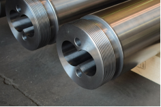
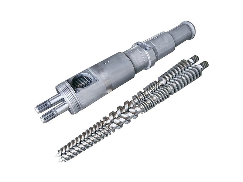
Figure 3. Close view of a parallel twin-screw barrel and its paired bore. Element selection must be checked against the installed barrel geometry and connection interfaces.
Prepare a Quote That Can Be Checked
· Extruder make, model, serial number, rotation direction, center distance, screw diameter, and barrel arrangement.
· Original element list or a position-by-position sketch, with part codes, lengths, pitch, disk angle, flight direction, and shaft connection.
· Polymer grades, filler or fiber levels, additives, recycled content, throughput, screw speed, torque trend, and temperature profile.
· Photos and measurements of the existing elements, shaft splines, and barrel bore, especially at worn or scored sections.
· A statement of whether the order is a direct replacement or a process redesign, plus the acceptance checks expected after installation.
Conclusion
The right screw elements for a twin screw extruder are the ones that fit the machine and serve a defined process function in the complete sequence. Confirm architecture and dimensions first, choose conveying and kneading geometry from the formulation and line evidence, then specify material protection and inspection requirements. That approach makes both replacement pricing and production trials more meaningful.
Related PIPLL Pages
· Parallel Twin Screw Barrel - Product category and machine-architecture context.
· Bimetallic Screw Barrel - Material protection for abrasive or corrosive duties.
· PIPLL Manufacturing Process - Machining, treatment, and inspection overview.
· Extruder Screw Wear Diagnosis - Operating signals to record before disassembly.
Technical and Sales Contact
Young | PIPLL | Screw and Barrel Solutions for Plastic Extrusion
Supporting extrusion manufacturers with customized screw and barrel solutions for PVC, PE, PP, PET, and other polymer processing applications.
Email: Young@pipll.com | WhatsApp: +86 150 5840 4692 | Website: www.pipll.com


+86 15267878906

1306 W building , NB-IoT Industrial Park, No. 199 Changxing Road, Jiangbei, Ningbo.
 Languages