 Languages
Processing High CaCO3 Filled Polymers
Processing High CaCO3 Filled Polymers: How Screw Flight Design Prevents Melt Instability
1. Economic Drivers & Rheological Challenges of High Filler Loading
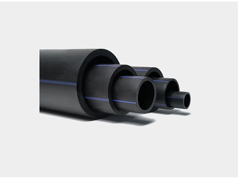
Incorporating high volumes of Calcium Carbonate (CaCO3), Talc, Barium Sulfate, or Glass Spheres into Polyethylene (PE) and Polypropylene (PP) is a core strategy across film, sheet, pipe, and profile manufacturing. Adding mineral fillers lowers resin costs, improves part stiffness, elevates heat deflection temperatures (HDT), and improves dimensional stability during molding or shaping.
However, increasing filler ratios past 20%—reaching up to 50% to 70% PHR (Parts Per Hundred Resin)—radically alters the melt rheology inside the extruder. High solid loadings convert fluid polymer melt into a dense, non‑Newtonian suspension. This creates exponential viscosity increases, strong resistance to shear thinning, and extreme wall friction along the screw channel and barrel wall.
⚠️ Processing Risk: Highly filled polyolefins processed with standard screw setups frequently suffer severe pressure surges, un‑dispersed filler agglomerates, and excessive friction‑induced thermal degradation.
GET A FREE QUOTE NOW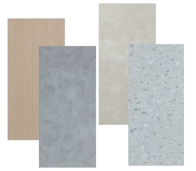
2. Processing Defects Stemming from Unoptimized Screw Geometry
Using off‑the‑shelf, general‑purpose screw profiles to process highly filled compounds typically leads to substantial product defects and process instability:
A. Pressure Surging & Unstable Extrusion Head Dynamics
Standard feed zones fail to compact dense mineral‑resin mixtures uniformly. Irregular compaction generates pressure fluctuations at the die head, causing variable wall thickness, sheet gauge variation, and frequent sizing adjustments in pipe lines.
B. Filler Agglomeration & Surface "White Specks"
Without targeted dispersive shear, microscopic CaCO3 particles bind together into hard agglomerates. These un‑dispersed clusters appear as visible "white specks" on extrudates, creating stress concentration points that significantly lower impact resistance and tensile strength.
C. Thermal Degradation, Die Drool, and Burned Spots
High solid loading generates excessive frictional shear heat in tight screw channels. If dead spots exist in the screw profile, localized resin matrix overheating occurs, resulting in thermal degradation, persistent die drool, and black specks in finished goods.
3. Parametric Analysis: Standard vs. High CaCO3 Custom Screw Profiles
The matrix below contrasts standard multi‑purpose screw parameters with specialized geometry engineered for high mineral loading:
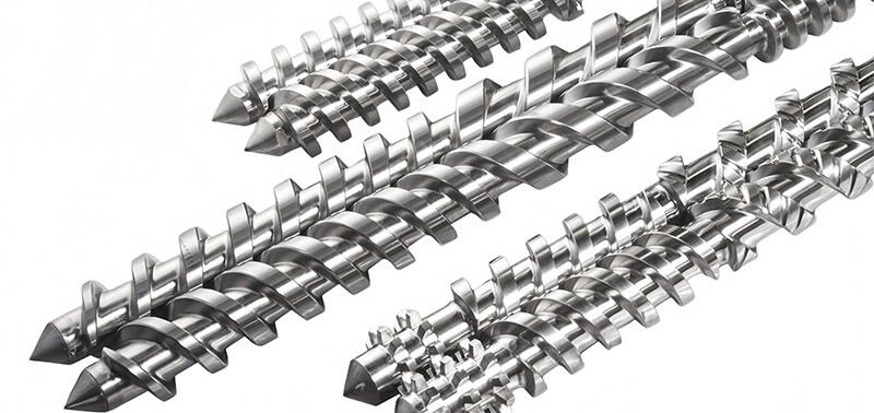
Flight Design Parameter Standard General‑Purpose Screw High CaCO3 Custom Engineered Screw Engineering Rationale Compression Ratio High (3.0:1 ‑ 3.5:1) Gradual / Moderate (2.0:1 ‑ 2.5:1) Prevents air entrapment and feed throat compaction bridging. Mixer Configuration Simple Pins / Standard Maddock Staggered Kneading Blocks + Dispersive Rings Delivers high‑shear dispersion without thermal degradation. Flight Pitch Profile Constant Pitch (1.0D) Variable Pitch (Decreasing toward Metering) Manages density increase smoothly while maintaining pressure buildup. Flight Clearance Standard Clearance (0.15 ‑ 0.25 mm) Tight Clearance (0.08 ‑ 0.12 mm) Reduces back‑leakage of low‑viscosity filled melt. Barrel Metallurgy Standard Nitrided Layer (0.5 mm) Nickel‑Chrome / Tungsten Carbide Bimetallic Resists continuous micro‑abrasion from mineral particles. 4. Engineering & Geometry Solutions for High CaCO3 Compounding
Achieving smooth, high‑output extrusion with 50%+ mineral loading requires specific design adjustments:
A. Variable Pitch & Gradual Tapering
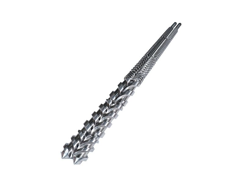
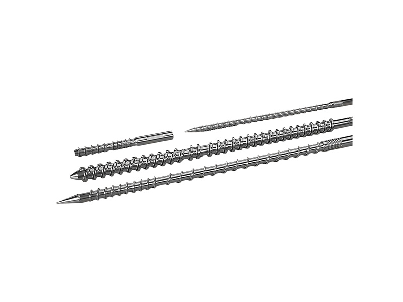
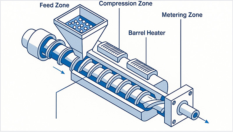
Transitioning from long pitches in the feed zone to shorter pitches near the metering section compresses dense powder‑pellet mixtures smoothly. This prevents sudden air entrapment, eliminates feed neck bridging, and ensures consistent volumetric delivery.
B. High‑Shear Dispersive & Distributive Mixing Sections
Effective dispersion relies on balancing dispersive mixing (breaking agglomerates apart) with distributive mixing (spreading particles evenly through the polymer matrix):
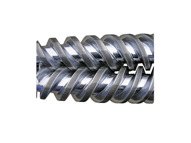
- · Staggered Kneading Elements: Positioned at 30° or 45° forward angles to subject agglomerates to high peak shear stress.
- · Grooved Barrier Elements: Prevent un‑melted filler clusters from passing down the channel until fully dispersed.
C. Matching High‑Hardness Bimetallic Protection
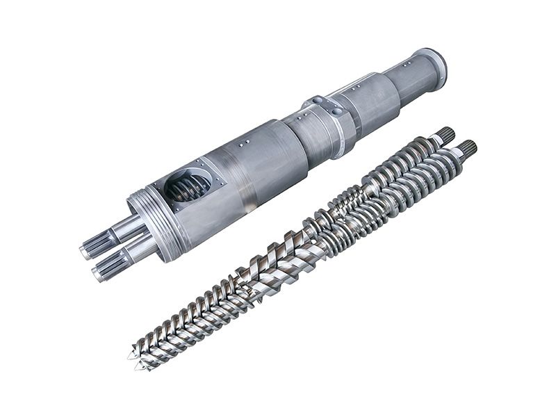
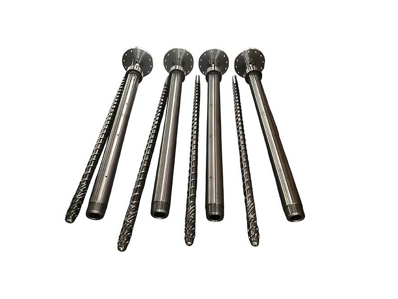
Because mineral particles act as persistent micro‑abrasives, advanced screw geometries must be matched with Nickel‑Chrome or Tungsten Carbide bimetallic barrels. High surface hardness prevents flight degradation, preserving exact channel geometries across years of high‑volume output.
5. Summary Troubleshooting Matrix for High Fillers
- · Problem: Die Drool ➔ Solution: Increase barrel temperature in devolatilization zone; reduce compression ratio to lower local frictional heat.
- · Problem: White Specks on Sheet Surface ➔ Solution: Add high‑shear dispersive mixing elements; verify surface treatment of CaCO3 powder (e.g., stearic acid coating).
- · Problem: Head Pressure Surging ➔ Solution: Optimize feed zone temperature cooling; switch to a gradual variable‑pitch feed screw.
PIPLL Engineering Solutions & Direct Support
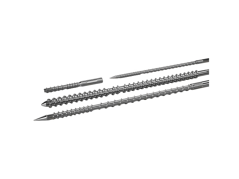
About PIPLL Engineering (www.pipll.com): PIPLL specializes in custom‑engineered screw and barrel assemblies built to withstand severe processing environments—from post‑consumer PET/PCR recyclates to ultra‑high CaCO3 mineral loadings. Manufactured leveraging Zhoushan's extrusion engineering hub and export facilities in Ningbo, PIPLL delivers precision component solutions worldwide.
Why Global Plastics Processors Partner with PIPLL:
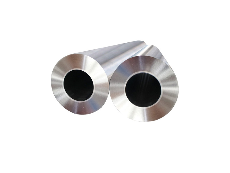
- · Centrifugally Cast Bimetallic Excellence: Our bimetallic barrels feature thick 2.0 mm to 3.5 mm alloy linings (PTA laser‑clad & Tungsten Carbide) with surface hardness up to 1800 HV, delivering 3x to 5x longer operational lifespan than standard nitrided components.
- · Application‑Specific Geometry Customization: Every screw assembly is designed to match your specific polymer viscosity, melt flow index (MFI), filler ratio, and target output rates.
- · Strict Quality Control & Global OEM Fit: Utilizing advanced 3D laser scanning and Coordinate Measuring Machine (CMM) inspection, PIPLL ensures tolerance matching within 0.02 mm for exact drop‑in fitment across global equipment brands.