How screw geometry, mixing strategy and wear-resistant metallurgy work together in highly filled PE and PP
Calcium carbonate, talc and barium sulfate are widely used in PE and PP to reduce formulation cost and improve stiffness, dimensional stability and other performance characteristics. As filler loading rises, however, the compound behaves very differently from the unfilled polymer.
High mineral loading can increase apparent viscosity, change flow behavior and increase the amount of solid material moving through the screw and barrel. If screw design is not matched to the formulation, the result can be higher torque, pressure fluctuation, poor dispersion, excessive wear and local overheating.
The goal is not simply to create more shear. A successful high-CaCO₃ screw balances conveying, melting, distributive mixing, dispersive mixing, pressure generation and residence time.
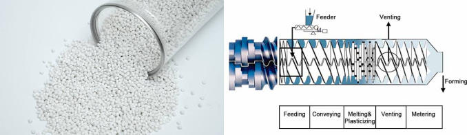
An unsuitable feed and compression profile can create unstable solids conveying and inconsistent melt formation. The resulting pressure variation may affect output consistency, dimensional accuracy and downstream die stability.
If the screw provides insufficient mixing, mineral particles may remain unevenly distributed. If the screw applies excessive shear or residence time, the polymer matrix can overheat. The design challenge is controlled mixing without unnecessary thermal stress.
Dead zones, excessive local shear and poor temperature control can cause degraded polymer to accumulate. In severe cases this can contribute to die drool, discoloration and black specks.
Mineral fillers can act as continuous abrasives. At high loading and throughput, wear can become a major factor in maintaining screw-barrel clearance and process stability.
| Design factor | General-purpose approach | High-CaCO₃ application |
|---|---|---|
| Compression | Often relatively aggressive | Usually more gradual; optimized for feedstock |
| Pitch | Often constant | May be varied to balance conveying and pressure |
| Mixing | Basic mixing section | Dedicated mixing selected for formulation |
| Solids conveying | Standard feed section | Designed around bulk density and filler loading |
| Wear protection | Standard nitrided hardware | Higher wear resistance where justified |
| Process target | General-purpose output | Stable pressure, dispersion and temperature |
A gradual change in channel volume can help avoid abrupt compaction and excessive local pressure. The optimum compression profile depends on polymer type, filler percentage, feeding method and target output; there is no universal compression ratio for every CaCO₃ formulation.
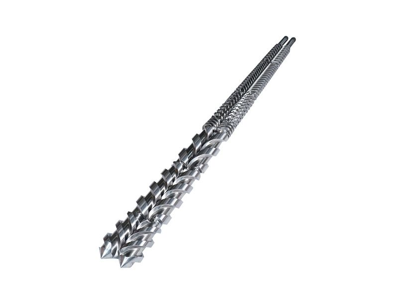
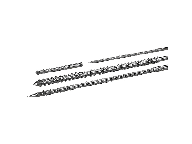
Changing flight pitch along the screw can be used to manage solids conveying, melting and pressure generation. The objective is a stable transition from feed to melt rather than simply maximizing compression.
Kneading blocks, Maddock-type mixers and other mixing elements should be positioned according to the desired melting and dispersion sequence. For highly filled compounds, the mixing strategy should be validated against torque, melt temperature, pressure and filler dispersion.
When mineral loading is high, wear-resistant metallurgy can protect the dimensional relationship between screw and barrel. Depending on the application, nickel-based alloys, tungsten-carbide-containing systems or other wear-resistant solutions may be appropriate.
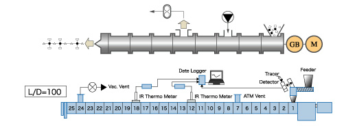
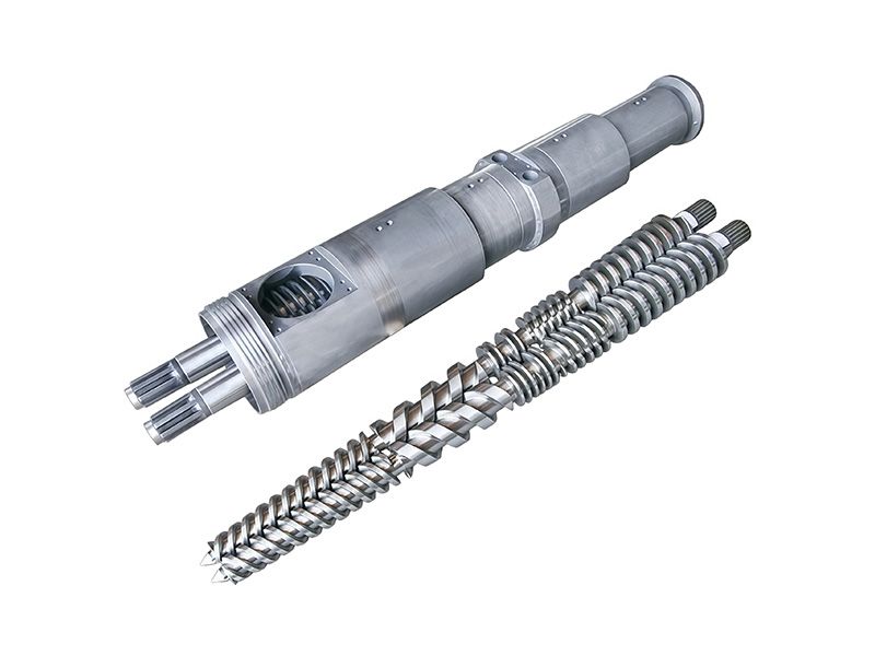
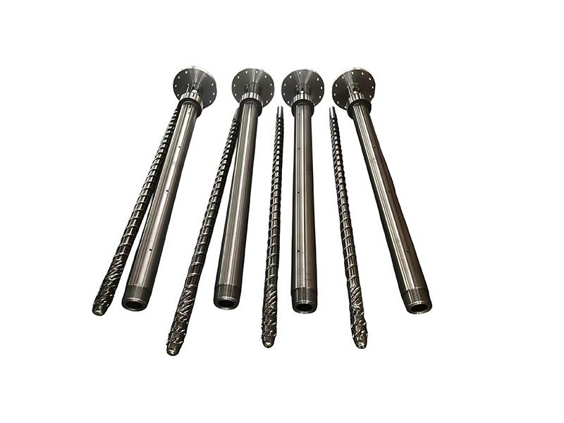
For abrasive mineral-filled compounds, geometry alone is not enough. The screw and barrel form a working system: as wear changes the flight land and barrel clearance, conveying efficiency, leakage flow and pressure generation can also change. Selecting wear-resistant surfaces helps preserve the designed geometry for longer.
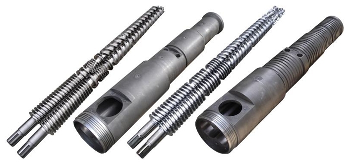
PIPLL designs and manufactures custom screw and barrel assemblies for demanding extrusion and compounding applications. Instead of applying one standard geometry to every formulation, we evaluate polymer, filler loading, feeding method, throughput and operating window to develop a practical screw configuration.


+86 15267878906

1306 W building , NB-IoT Industrial Park, No. 199 Changxing Road, Jiangbei, Ningbo.
 Languages
