Twin Screw Extruder L D Ratio and Melt Overheating — What to check when a formulation moves from 36 to 48 L D
You move a filled compound from a 36 L/D line to a 48 L/D line. Output rises, but the strands become yellow or brittle. Lower barrel settings seem to make little difference. The longer machine has more room for processing tasks, yet the transferred recipe and operating settings still need a review.
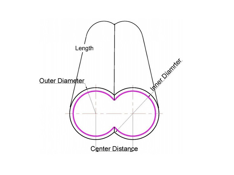
The twin screw extruder L/D ratio describes processing length relative to screw diameter. It helps describe the machine, while the element layout, feed rate, rpm and heat transfer determine the conditions experienced by the material. PIPLL uses those details when discussing a screw and barrel application.
What Changes When the Screw Gets Longer
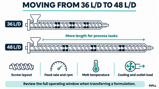
At the same diameter, moving from 36 L/D to 48 L/D adds one third to the processing length. Extra length can accommodate melting, staged feeding, mixing, venting or pressure generation.
Figure 1. Schematic layouts highlight the process variables to review when moving to a longer screw.
The residence time and cumulative mixing exposure depend on how that space is used. Restrictive elements, local fill, throughput and outlet resistance can change material hold-up. Measure the response on the new line instead of estimating residence time from length alone. PIPLL residence time guide .
If the new machine also has a larger diameter, the same rpm gives a higher screw tip speed. Its volume also grows faster than its available heat transfer area. Diameter, free volume and cooling capacity therefore belong in the transfer review. Thermo Fisher's scale-up note shows why feed rate and process measurements need adjustment between machines. Twin screw process parameter study .
Adjust Rpm and Feed Rate as a Pair
Establish the New Operating Baseline
Record the exact formulation, moisture where relevant, output, screw speed, shaft power or torque, actual melt temperature and head pressure. Add vacuum conditions, cooling demand and a quality measurement such as melt flow rate, viscosity, dispersion or retained fiber length.
On a starve-fed co-rotating twin screw, rpm and throughput interact. Reducing rpm at constant throughput often raises fill and load. Raising feed at constant rpm can reduce mechanical energy per kilogram in some operating windows, but the line must still melt the feed, accept side-fed material and vent effectively. Coperion illustrates the relationship between rate, fill and energy input. Efficient compounding technical presentation .
Use the same throughput for an initial rpm comparison where practical. Make a small controlled change within machine limits, stabilize the process and compare melt temperature, load and quality. Then evaluate feed rate separately. Avoid prescribing one percentage reduction for every resin and screw configuration.
Compare Mechanical Energy per Kilogram
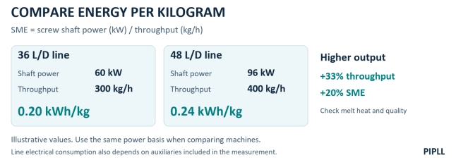
Specific mechanical energy in extrusion, SME, can be calculated as screw shaft power in kW divided by throughput in kg/h, giving kWh/kg. If power is estimated from electrical input or a drive display, account for what that reading includes and use the same calculation basis on both lines.
At 60 kilowatts and 300 kilograms per hour SME is 0.20 kilowatt hours per kilogram. At 96 kilowatts and 400 kilograms per hour SME is 0.24.
Figure 2. Illustrative shaft power and output values show a rise in both throughput and SME.
The example shows why a higher production rate can coexist with higher mechanical energy per kilogram. Compare SME with measured melt temperature and the product result. Different layouts can distribute the same total energy very differently along the screw.
For extruder specific energy consumption at line level, define whether the measurement includes heaters, cooling, vacuum and downstream equipment. Keep that electrical energy measurement distinct from shaft-based SME. A higher SME warrants investigation, while degradation still needs a material or quality check.
Rebuild the Temperature Profile Around Process Tasks
Check Melting Before the First Intensive Mixing Section
Review the resin supplier's melt window and the location of the first restrictive elements. If the screw is forcing poorly softened material through an intensive mixing section, inspect the upstream heating, rate and geometry together. Enough heat and exposure must be available for reliable melting.
Keep feed throat cooling and intake conditions suitable for the material. Use actual melt measurements and samples to decide whether a change in the early heated zones helps. A cold feed throat and a heated melting section perform different jobs.
Remove Excess Heat Where the Melt Is Being Worked
Once the material is molten, mechanical work can supply substantial heat. Check whether the affected barrel zones are heating or calling for cooling, and verify cooling flow, valve operation and heat exchanger condition. A low setpoint with cooling continuously demanded can indicate limited heat removal or excessive local energy input.
Trial a lower setpoint only within the validated processing window. A colder wall can increase local viscosity and drive load, so log the response in melt temperature and torque. Select the profile from the material and operating data rather than applying the same 10–20°C reduction across every mixing zone.
Keep Venting and Discharge Conditions in Balance
At a vent, review local fill, pressure, vacuum performance and carryover. At the discharge, compare actual melt temperature, head pressure and the filter condition. Excessive cooling can increase viscosity and outlet resistance. Excess temperature or moisture can damage the material, depending on the resin.
A useful review map follows feed, melting, side feeding, mixing, venting and discharge. Those task locations matter more than copying the old zone numbers onto the longer barrel.
Inspect Restrictions and Match the Hardware to the Duty
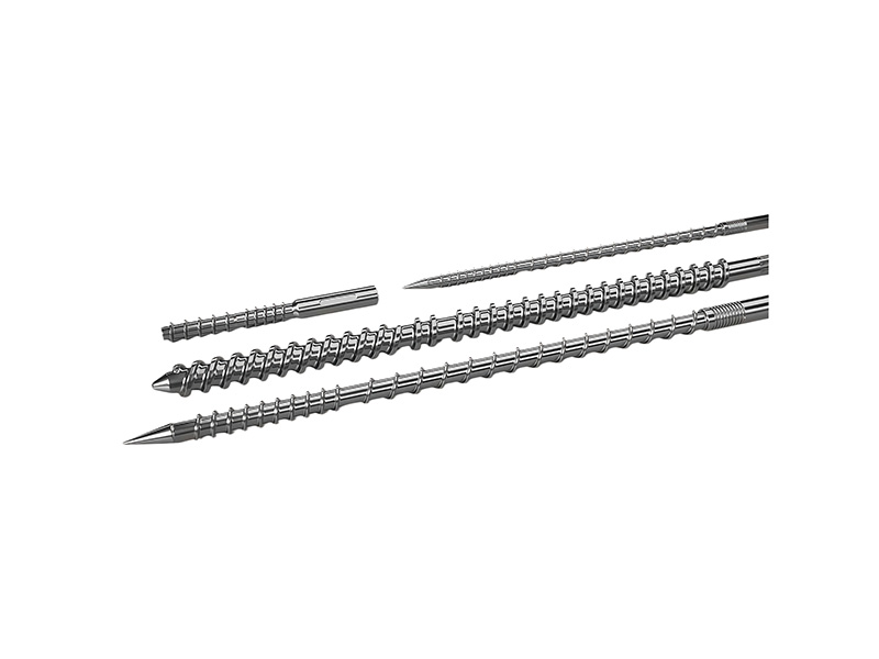
Review the element map. Locate the kneading blocks, reverse elements and pressure seals on both screws. Check disk width, stagger angle, handedness and the neighboring conveying sections. A longer screw may allow a gentler arrangement for some tasks, while pigment breakup may still need a targeted dispersive section. Validate dispersion and fiber properties after a layout change. PIPLL twin screw element guide .
Review the outlet load. Compare screen pressure drop where measured, adapter and die condition, and pressure trends at the target output. Clean or service a restricted path. Any screen configuration change must still meet filtration and product requirements. A lower head pressure alone does not confirm that a revised setup makes acceptable material.
Bring PIPLL the Layout and the Measurements
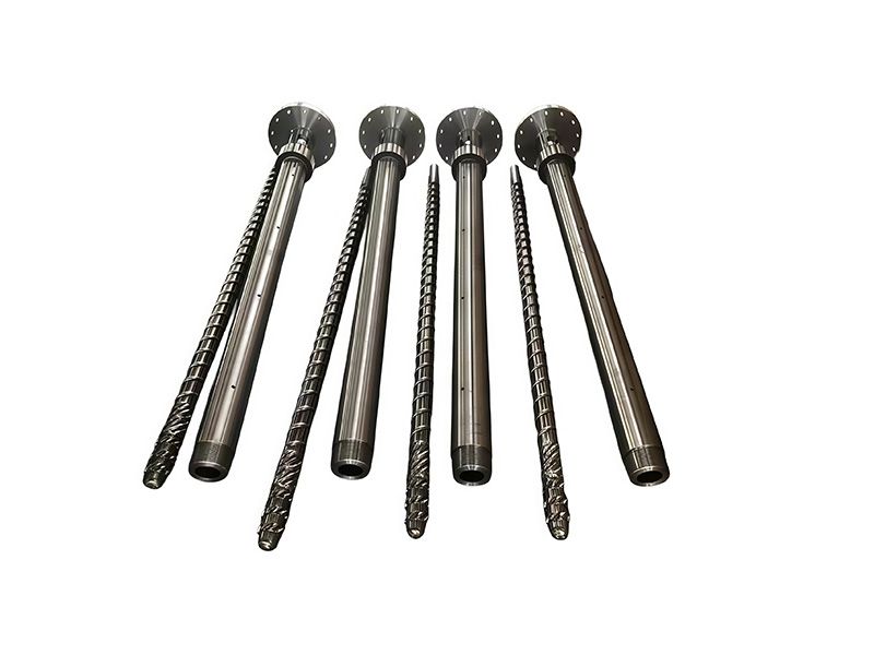
PIPLL's customization process connects machine dimensions, screw geometry and material duty. For a 36 to 48 L/D transfer, provide both screw maps, diameter, free volume information if available, motor and gearbox limits, feed and vent locations, and the baseline readings. These inputs help focus a discussion on element arrangement, clearances and cooling provisions. PIPLL custom screw and barrel service .
For filled formulations, include a screw wear measurement report and matching barrel bore readings where wear is suspected. Review the required abrasion and corrosion resistance against the formulation when selecting a lining. Confirm the barrel geometry and machine fit for any product under consideration. PIPLL bimetallic extrusion barrel .
Agree drawing dimensions, metallurgy and inspection records for the replacement. That gives the process review a clear connection to the manufactured components. PIPLL manufacturing process .
Frequently Asked Questions
Does 48 L/D mean one third longer residence time? Length rises by one third at constant diameter. Residence time depends on hold-up, feed rate, screw layout and downstream resistance. A tracer trial can compare the actual response.
Should every longer screw run at lower rpm? Choose the rpm and feed rate together from melting, load, venting and quality limits. Validate the change on the actual machine.
Do yellow strands prove mechanical degradation? Yellowing can also involve moisture, contamination, oxidation, additives or material held up in hot areas. Compare the run history and relevant material properties to identify the cause.
Discuss the Transfer with PIPLL
Send the old and new machine details, formulation, element maps and a log of output, rpm, power, melt temperature and pressure. Add defect photos and the quality test results. PIPLL can use them to discuss which process sections and component measurements to review. Contact PIPLL .
Technical and Sales Contact
Harry Jiang | PIPLL
Email: harry@pipll.com | WhatsApp: +86 182 6854 1152
Website: www.pipll.com


+86 15267878906

1306 W building , NB-IoT Industrial Park, No. 199 Changxing Road, Jiangbei, Ningbo.

 Languages