What to verify after delivery and before installation
An extruder screw barrel acceptance inspection checklist should connect each delivered part to the approved drawing, material specification, and inspection record before installation. Begin with the agreed custom screw and barrel requirements, compare the supplied reports with the PIPLL manufacturing process , and identify the treatment or lining specified for a bimetallic screw barrel where applicable. A polished surface and a packing list cannot establish that critical dimensions and material requirements have been met.
This checklist is for engineering, purchasing, and maintenance teams receiving a new or replacement assembly. Agree on acceptance criteria before manufacture, then use delivery inspection to confirm identity, condition, interfaces, and documented results. Record unresolved differences before the parts enter service.
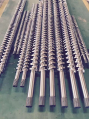
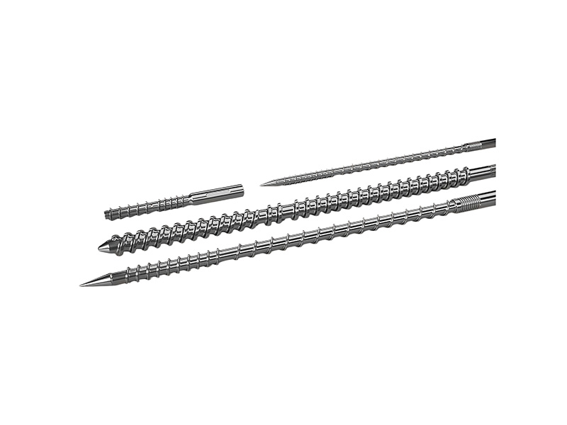
Figure 1. Screw assemblies with different profiles and drive ends. Match each delivered component to its drawing and identification record.
Check Identification and Transport Condition
Photograph the packaging and supported component positions before unpacking. Check for impact marks, corrosion, damaged threads, missing protection, and contamination. Compare part numbers, quantities, serial or batch references, and drawing revisions with the order. For twin screws, preserve the agreed pair identification and orientation. Confirm that the shipping restraints and lifting arrangement are suitable before moving a long or heavy part.
Keep the approved drawing beside the inspection sheet. A worn sample, an old quotation, or a nominal machine diameter should not silently replace the released specification. If the assembly was redesigned, identify the changed features so the receiving team does not judge the new part against an obsolete drawing.
Measure the Geometry That Controls Fit
Check | Record | Acceptance basis
Screw flight and root dimensions | Axial station, angular position, diameter and relevant profile features. | Approved profile drawing and defined tolerances.
Barrel bore after delivery | Bore size at specified stations and directions, with gauge reference. | Approved bore geometry and measurement plan.
Drive and end connections | Spline or key form, threads, flange faces and bolt pattern. | Mating machine interfaces and drawing revision.
Openings and barrel zones | Feed and vent location, sensor holes and heater or cooling interfaces. | Installed line layout and approved barrel drawing.
Runout and straightness | Datum, support arrangement, stations and total indicator reading. | The specific runout or straightness requirement on the drawing.
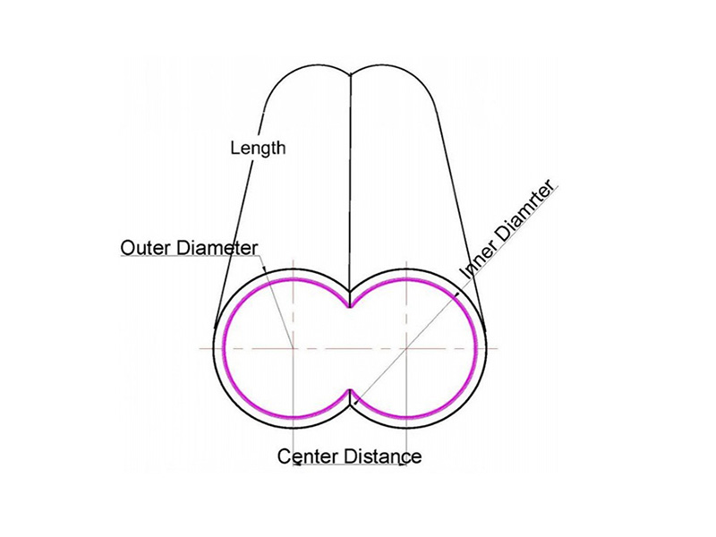
For barrel bore measurement after delivery, use calibrated equipment suited to the bore length and geometry. Identify the gauge setting, reference temperature, operator, and locations measured. A single reading at the accessible end does not describe the full working length. Compare corresponding screw and barrel dimensions and state whether the reported clearance is diametral or radial.
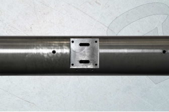
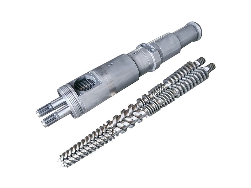
Figure 2. A machined opening on a barrel body. Opening position, bolt pattern, and surrounding interfaces belong in the dimensional inspection.
Interpret Runout and Profile Checks Correctly
A screw straightness TIR check needs a documented setup. Total indicator reading is the difference between maximum and minimum readings during rotation at a stated position. Its meaning depends on the support and datum, so TIR and geometric straightness are not interchangeable labels. Record the fixture arrangement and compare each result with the requirement actually specified.
If you check compression ratio by root diameter, use the approved screw design method. Flight and root diameters define channel depth, but the ratio of two root diameters is not the compression ratio. Changes in pitch, flight width, or channel geometry can require a fuller channel volume calculation. For a twin screw, use the applicable profile and architecture rather than a simplified single screw rule.
Review Material and Treatment Evidence
The screw barrel inspection report contents should include part identity, material designation, measured results, drawing limits, method, and instrument identification. Add the material certificate, agreed heat treatment or coating record, and any required surface or lining reports. Ensure the certificates are traceable to the delivered parts or their manufacturing batch.
A portable screw hardness test, including Leeb testing where suitable, does not by itself prove a nitrided case depth. Confirm the method and load appropriate to the material and geometry. A nitrided case depth check generally needs an agreed sectioned specimen or representative process coupon with a defined hardness profile method. For alloy linings, any ultrasonic bond test must use a procedure suitable for that construction and the acceptance criteria agreed in the order.
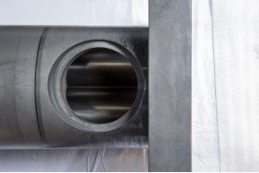
Figure 3. Barrel opening with the internal working surface visible. Visual inspection complements the bore report and cannot replace measurements along the working length.
Document the Decision Before Installation
• Release the parts when identity, condition, required reports, and measured critical features meet the agreed specification.
• Hold a part when a critical measurement, report, or drawing reference is missing and obtain clarification before installation.
• For a confirmed discrepancy, record the actual result, required limit, method, photographs, and part identification, then agree on disposition with the supplier.
Installation and a controlled production trial provide the next evidence. Check alignment and follow the machine procedure, then record output, pressure, temperature, and product quality at the agreed operating point. Preserve the receiving report as the dimensional baseline for later maintenance inspections.
Conclusion
A useful extruder screw barrel acceptance inspection checklist makes every release decision traceable to an approved requirement. Check the delivered identity and interfaces, measure critical geometry with a defined method, and verify material and treatment evidence. Resolve gaps before installation so the new assembly begins service with a usable inspection record.
Related PIPLL Pages
• Pipe and Tube Extrusion Screw Barrel
– Related product page.
• Plastic Compounding Twin Screw Barrel
– Related product page.
• Extruder Screw Wear Diagnosis
– Technical article.
• Screw Barrel Maintenance Guide
– Technical article.
Technical and Sales Contact
Young | PIPLL | Screw and Barrel Solutions for Plastic Extrusion
Supporting extrusion manufacturers with customized screw and barrel solutions for PVC, PE, PP, PET, and other polymer processing applications.
Email: Young@pipll.com | WhatsApp: +86 150 5840 4692
Website: www.pipll.com


+86 15267878906

1306 W building , NB-IoT Industrial Park, No. 199 Changxing Road, Jiangbei, Ningbo.
 Languages