A practical guide to temperature, pressure, speed, time and position — and how they interact across the molding cycle to control fill, packing, shrinkage and part quality.
Five injection molding parameters shape much of what happens inside the barrel and mold: temperature, pressure, speed, time and position. Understanding their connections makes troubleshooting more systematic. A sink mark may involve packing, gate sealing or material delivery; flash may involve transfer timing, cavity pressure or tooling condition.
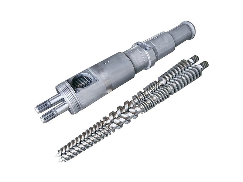
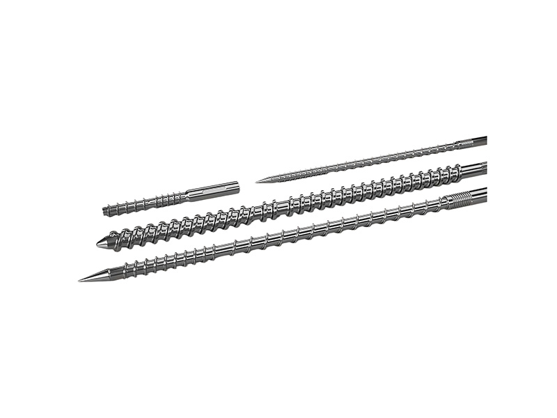
This guide connects the settings to the molding cycle and explains when to inspect the plasticizing unit. As a screw and barrel manufacturer , PIPLL considers material behavior and component condition together when reviewing processing requirements.
How the Five Injection Molding Parameters Connect
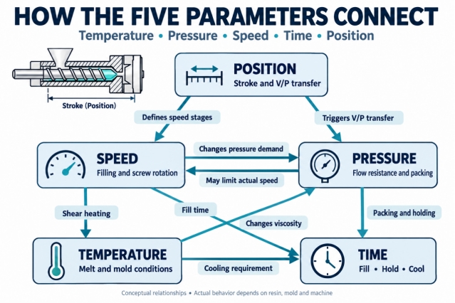
The screw prepares the melt. Controlled-speed filling delivers it to the cavity within a pressure limit. V/P transfer starts packing and holding, which compensate for shrinkage while the gate can still transmit material. Cooling continues until the part can be ejected. Each stage sets the conditions for the next: changing temperature, speed or transfer timing can alter both pressure demand and the time needed for a stable part.
Figure 1 — How the five parameters influence each other across the molding cycle.
Temperature Establishes the Processing Window
Separate barrel settings from actual melt temperature
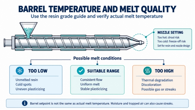
On an injection molding machine screw barrel, the barrel-zone settings describe heater control targets. They do not directly measure the temperature of the plastic leaving the nozzle. Screw rotation, back pressure, throughput and residence time also affect the melt.
Start with the processing guide for the exact resin grade. Verify actual melt temperature using an approved measurement procedure when investigating thermal problems. A nozzle setting should suit the resin, nozzle design and cycle; it does not always need to be lower than the front barrel zone.
Insufficient heat can cause poor melting and high flow resistance. Excessive temperature or residence time can promote degradation. Silver streaks alone do not prove overheating: moisture, trapped air and contamination also need investigation.
Figure 2 — Barrel temperature affects melt quality; nozzle settings depend on the resin and equipment.
Control mold temperature and cooling uniformity
Mold temperature affects surface replication, solidification, residual stress and shrinkage. For semi-crystalline materials such as PA and POM, it also affects crystallization and subsequent dimensional behavior. The outcome depends on the grade, reinforcement, part geometry and conditioning requirements.
Check actual mold-surface temperatures and coolant flow, not just the temperature controller display. Uneven cooling can produce warpage even when the average mold temperature looks correct.
The interaction: after changing melt or mold temperature, recheck fill behavior, transfer, packing effectiveness and cooling. Allow the tool and material to stabilize before comparing results.
Pressure Enables Filling and Controls Packing
Injection pressure and holding pressure have different jobs
During velocity-controlled filling, the machine develops pressure to achieve the programmed injection speed. The pressure setting commonly acts as a limit. If that limit is reached, actual speed may fall below the command and fill time may increase. Lowering the pressure limit simply because the part looks full can therefore make filling inconsistent. Check the machine’s control mode and actual pressure and velocity traces.
After transfer, packing and holding pressure compensate for cooling shrinkage while material can still pass through the gate. Insufficient packing can contribute to sinks and voids. Excessive packing can cause flash, difficult ejection and residual stress. More pressure cannot reliably correct a gate that has already sealed.
Machine pressure is also different from cavity pressure. Pressure losses through the nozzle, runner and gate matter. When comparing presses, distinguish hydraulic pressure from specific plastic pressure and confirm the units and conversion used.
Back pressure acts during screw recovery
Back pressure resists screw retreat as the next shot is prepared. It can improve melt consistency and color dispersion, but increasing it can also increase shear heating and extend recovery. It is not a replacement for correct drying or a suitable screw design. Fiber-filled and heat-sensitive grades need particular care.
The interaction: when back pressure changes, monitor melt temperature, recovery time and shot consistency. A setting intended to improve mixing can change both the thermal state and the available cycle time. For a PIPLL component inquiry, record these trends together so the operating issue is clear.
Speed Changes Flow and Heat Generation
Injection speed controls how quickly material enters the mold. Screw rotational speed controls how the next shot is plasticized. They need separate evaluation.
A slower initial injection segment may reduce jetting as melt enters an open cavity. A faster main fill can help material reach thin sections before excessive cooling. Deceleration near the end of fill can reduce pressure overshoot and trapped-air burning. These are possible responses to the flow path, not a universal slow-fast-slow recipe. Gate geometry, venting, material sensitivity and machine response determine the useful profile.
Faster flow also changes shear rate. The resulting shear thinning and heating affect pressure demand, so faster filling does not produce one predictable pressure change in every application. Diagnose burns and streaks by location and process evidence rather than assuming that speed alone caused degradation.
Higher screw rpm can shorten recovery but may increase melt temperature or damage reinforcing fibers. Evaluate recovery against the available cooling window, together with back pressure and melt quality. Share the screw diameter, operating rpm and recovery trend with PIPLL when discussing screw geometry or replacement requirements.
The interaction: after changing injection speed, review actual fill time, pressure demand and the V/P transition. After changing screw speed, review temperature and recovery consistency.
Time Determines Whether Each Stage Finishes Its Job
Establish hold time with a gate seal study
With temperature, filling and holding pressure stable, increase hold time in controlled steps. Collect several samples at each condition, identify cavities where relevant and weigh parts consistently. Plot part weight against hold time.
A repeatable weight plateau indicates that additional holding is no longer adding meaningful material under those conditions. Confirm dimensions and appearance, then allow a validated margin above the minimum effective time. Valve-gated and some hot-runner processes require an approach matched to their gate behavior.
A flat weight curve can also be misleading if the screw bottoms out or material delivery is faulty. Confirm a usable cushion and reliable pressure transmission before treating the plateau as proof of gate sealing.
Optimize cooling without confusing timer labels
Cooling starts as soon as melt contacts the mold, including during filling and holding. The machine’s separate cooling timer may represent only the time after hold; check its sequence before comparing cycle data.
Choose an ejection condition that meets deformation, surface and dimensional requirements. Wall thickness, actual melt temperature, cooling-channel performance and resin behavior all matter. Cooling can be a major cycle constraint, but its share of the cycle varies. Measure the actual bottleneck rather than targeting a fixed percentage.
Recovery must finish within the available machine sequence with suitable operating margin. If it becomes the bottleneck, check feeding, back pressure, screw speed, heater performance and component condition before increasing rpm.
The interaction: shortening hold or cooling can change part quality and material residence history. Verify the complete cycle, including operations that overlap.
Position Controls Transfer and Material Reserve
Use V/P transfer to manage the end of filling
The velocity-to-pressure transfer point defines when the machine leaves the filling phase and enters packing and holding. Transfer too early and the holding phase must perform excessive filling. Transfer too late and the process may develop a sharp pressure rise, flash or overpacking.
A controlled filling-only study can help establish an initial transfer point. Reduce or remove hold according to the approved setup method and progressively approach a nearly full cavity without overpacking. Inspect individual cavities and confirm the result using machine curves and cavity-pressure data where available.
The often quoted 95–98% fill range is a starting concept used in some material guides. It is not a universal setting and does not mean 95–98% of screw travel. Runners, melt compression, check-ring behavior and cavity balance affect the relationship between screw position and cavity fill.
Keep a repeatable cushion
Cushion is the remaining melt reserve ahead of the screw at its furthest forward position during hold. A usable reserve allows pressure to be transmitted without the screw reaching its forward travel limit. Its appropriate size depends on the injection unit and process; one millimeter value should not be applied to every machine.
Also record metering and decompression positions. Excessive decompression can introduce air, while insufficient decompression may allow drool in some setups. Validate both against the material and nozzle arrangement.
The interaction: transfer position means little without stable melt preparation and material delivery. If cushion and weight vary together, investigate the check valve, feeding and plasticizing conditions before chasing the transfer setting.
Three Defects That Reveal the Connections
The following are illustrative troubleshooting sequences, not reports of a particular production trial.
Sink marks despite higher holding pressure
First compare part weight, cushion and the response to hold time. If extending hold increases weight and reduces sinks, the original hold may have ended too soon. If extra hold has no effect, investigate early gate sealing, restricted pressure transmission, screw bottoming and local part thickness. Review mold cooling as well. Increasing pressure alone may overpack the gate area while leaving a thick section inadequately compensated.
Flash after increasing injection speed
Compare the actual end-of-fill pressure trace with the previous process. Faster filling can expose a late transfer or inadequate deceleration. Review the transition before reducing all injection pressure. Inspect parting surfaces, vents, tool support and clamp conditions too: damaged tooling cannot be repaired through parameter changes.
Part weight varies with an unchanged recipe
Trend fill time, pressure, minimum cushion, recovery time and part weight together. Check material lot, drying, regrind ratio and feeding. Once these are stable, use the machine maker’s approved check-valve test and inspect wear where indicated. An unchanged screen recipe does not prove unchanged melt delivery.
Injection Screw Barrel Checks to Discuss with PIPLL
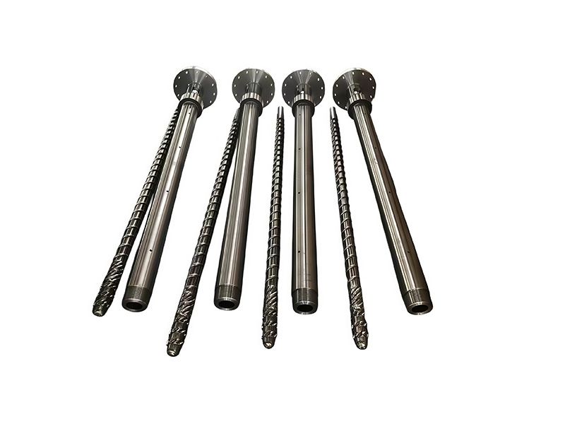
Persistent recovery drift, unmelted resin, unstable cushion or repeated compensation with higher temperature and back pressure justify reviewing the injection screw barrel. These symptoms do not prove that replacement is required. Check heaters, sensors, feeding and the check valve first, then measure screw-flight and barrel-bore wear against the machine maker’s criteria.
Nitrided or bimetallic injection screw barrel
A nitrided injection screw barrel may suit applications where its wear and corrosion performance meets the actual duty. A bimetallic injection screw barrel may deserve evaluation for abrasive or demanding formulations. Match the alloy, screw geometry and operating conditions to the resin and filler; a material name alone does not predict service life.
PIPLL’s bimetallic screw and barrel options introduce wear-protection approaches. The PIPLL bimetallic extrusion barrel product page provides a reference for alloy linings. An injection unit requires its own dimensional and check-valve assessment. Review inspection requirements alongside the PIPLL manufacturing process .
Prepare the right data for injection screw barrel replacement
Before requesting an injection screw barrel replacement, collect the machine model, screw diameter, L/D ratio, original drawing, connection dimensions and check-valve details. Include the resin grade, filler percentage, recovery trend and wear measurements. PIPLL’s custom screw and barrel review starts with this application context so the discussion can focus on fit, material selection and the observed problem.
A Practical Adjustment Sequence
1. Save the baseline recipe and record the defect, material condition and actual cycle data.
2. Stabilize drying, feeding, melt preparation, mold temperature and cooling flow.
3. Establish repeatable filling and transfer without using excessive hold to hide a filling problem.
4. Verify holding pressure and effective hold time, then optimize cooling and recovery.
5. Change one selected setting at a time during initial troubleshooting. Record both the setting and the measured response.
6. Evaluate only after relevant outputs have stabilized. Five to ten shots may show an initial trend, but temperature changes can require longer. Confirm quality over a representative production run; use a structured experiment when interactions need quantifying.
Frequently Asked Questions
Which injection molding parameter should I adjust first?
Choose from the evidence. Start by checking material preparation and actual thermal conditions, then locate whether the defect develops during filling, packing or cooling. There is no single first adjustment for every defect.
Can higher holding pressure always eliminate sink marks?
No. It helps only while pressure can transmit enough material to the affected region. Gate sealing, restrictions, unstable delivery and part design can limit its effect.
Why does actual injection speed fall below its setting?
The pressure limit or machine performance may be restricting the commanded motion. Check actual pressure, velocity and fill time before increasing the speed command.
Does an unstable cushion mean the screw must be replaced?
No. Check-valve sealing, feeding, melt consistency and control behavior also affect cushion. Confirm the cause through testing and measurements before deciding on a replacement.
Discuss Your Screw and Barrel Requirements with PIPLL
Stable injection molding parameters depend on repeatable melt preparation, controlled filling, effective packing and sufficient cooling. If adjustments keep masking a suspected component problem, contact PIPLL with your machine details, resin grade, drawing and defect photos. Tell Harry whether you need a wear review, material comparison or a screw and barrel set for an injection molding machine, so the required scope and fit can be confirmed.
Harry Jiang | PIPLL
Email: harry@pipll.com | WhatsApp: +86 182 6854 1152
Website: www.pipll.com


+86 15267878906

1306 W building , NB-IoT Industrial Park, No. 199 Changxing Road, Jiangbei, Ningbo.
 Languages