 Languages
Injection Screw Selection Understanding A B and C Options
-
-
Injection Screw Selection Understanding A B and C Options
Match diameter, pressure capacity and material requirements before ordering. When an injection molding machine supplier asks whether you want an A, B or C screw, choosing the middle option can feel convenient. Good injection screw selection starts with the actual shot requirement, filling pressure and material behavior, rather than the letter on the quotation.
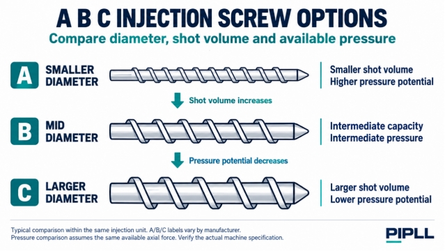
On many machine ranges, A identifies a smaller diameter, B an intermediate diameter and C a larger diameter within a particular injection unit. This is a common naming convention, not a universal specification. Confirm the diameters and ratings on the exact manufacturer's data sheet.
INJECTION SCREW SELECTION · A B C DIAMETER OPTIONS · SHOT VOLUME AND PRESSURE TRADEOFF · INJECTION SCREW BARREL REPLACEMENT
-
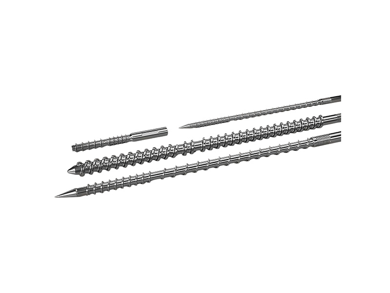
A B and C injection screw options showing smaller intermediate and larger diameters with typical capacity and pressure tradeoffs. Typical comparison within the same injection unit. A/B/C labels vary by manufacturer.
-
What A B and C Usually Describe
Compare the options within the same injection-unit family. Smaller diameter generally offers less shot volume and greater pressure potential; larger diameter generally offers more volume and lower pressure potential. Machine makers publish different diameter options, effective L/D ratios and performance ratings for a given injection unit.
If effective screw length stays approximately unchanged, a smaller diameter produces a larger L/D ratio. But diameter and L/D do not describe the complete screw: channel depth, compression ratio, mixing features, check valve, materials and drive limits also matter.
PIPLL selection note: ask for the full injection-unit specification, not only the clamping tonnage or the A/B/C designation. Different injection units can be fitted to machines with the same clamp rating. -
Why Diameter Changes Pressure and Capacity
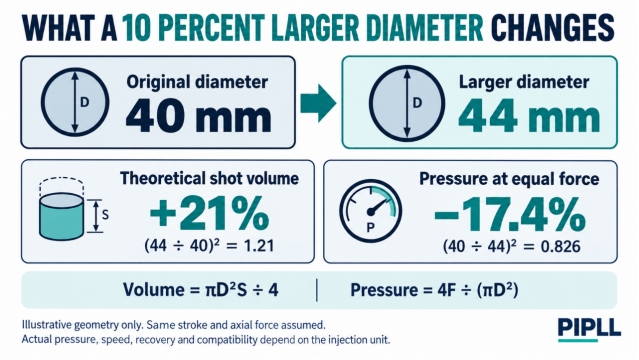
For screw diameter D and injection stroke S, the theoretical swept volume is proportional to the screw's cross-sectional area:
Theoretical swept volume = π × D² × S ÷ 4
For the same available axial injection force F, the corresponding specific plastic pressure is inversely proportional to that area:
Specific plastic pressure = 4 × F ÷ (π × D²)
Keep units consistent. These relationships explain the tradeoff; the machine maker's published limits govern the actual operating envelope. Hydraulic circuit pressure, specific plastic pressure and cavity pressure are different quantities.
-
Illustrative geometry for equal stroke and axial force. Changing diameter from 40 to 44 mm gives 21% more theoretical swept volume and approximately 17.4% less pressure at the same force. Actual machine performance requires an OEM specification check.
-
Check flow rate and recovery as well
At the same linear injection speed, a larger screw displaces more volume per second. However, the drive may not deliver its highest speed and pressure simultaneously. Thin-wall filling can require both, so maximum shot volume alone is an incomplete selection criterion. The machine data sheet's drive limitations matter.
Recovery must also finish within the available cycle. Compare the required shot, resin-specific plasticizing performance, screw rpm and cooling window. A high-pressure small screw that cannot prepare the next shot fast enough can become a cycle bottleneck.
-
When Each Diameter Option Deserves Consideration
A smaller screw for pressure demand and small shots
A smaller diameter is worth evaluating when a modest shot requires substantial filling pressure, or when the existing barrel is oversized for the application's throughput. Possible examples include small engineering components, long flow paths and some thin-wall parts.
For PC, PMMA, reinforced PA, PPS or PEEK, use the exact grade's processing guidance. High pressure cannot compensate for incorrect drying, an unsuitable gate or insufficient melt preparation. Some grades also require specific temperature capability, screw geometry, surface condition or wear protection.
A smaller plasticizing unit may reduce material inventory for a small-shot application, but residence time also depends on cycle time, throughput and the actual material held in the unit. Do not infer residence time simply by dividing the rated maximum shot by the product weight.
B as an intermediate option for a defined job mix
An intermediate diameter may suit a shop processing several materials and molds, provided the expected jobs fit its pressure, volume and recovery capabilities. PP, PE, ABS and HIPS applications can be candidates, but their grade, filler content and flow-path requirements still determine suitability.
For PIPLL application discussions, a useful starting point is a list of representative jobs: minimum and maximum total shot, resin grades, cycle times and filling conditions. That evidence is stronger than assuming B is the factory default or covers a fixed percentage of molding work.
C for larger shots with adequate pressure reserve
A larger diameter can help with higher-volume shots such as containers, housings or other parts whose filling conditions remain within the injection unit's pressure and flow envelope. A high-flow PP or PE grade may make that balance easier, but part geometry and gate design still matter.
Capacity does not establish machine suitability. Check clamp force, mold dimensions, opening and ejection requirements, injection flow and recovery. A large projected area or demanding thin-wall fill may require a different machine or injection unit even when C provides enough volume.
Quick comparison: evaluate A when pressure or small-shot matching dominates; B when a defined job mix fits the intermediate envelope; C when volume dominates and pressure, flow and recovery remain sufficient. -
Choose a Shot Utilization Range for the Actual Resin
Include all cavities, sprue and cold runners, and account for the material delivered during packing. Use the OEM's volume or material-specific shot-capacity convention consistently. Keep a suitable cushion and respect metering-stroke limits; a polystyrene shot-weight rating cannot be applied unchanged to every resin.
Volume utilization = required shot volume ÷ rated maximum shot volume × 100%
For example, a 50 cm³ requirement against a 100 cm³ rated maximum gives 50% on that basis. That ratio is a screening result, not proof that the process has sufficient pressure, recovery or thermal stability.
The often quoted 30–70% range is useful only with context. Follow the applicable grade and equipment guidance rather than adopting one universal window. Very small shots can create excessive residence time in an oversized unit; very high utilization can leave insufficient operating margin.
PIPLL recommends bringing the utilization calculation together with cycle data, actual melt condition, recovery trend and cushion behavior when discussing an injection molding machine screw barrel.
-
Transparent and Fiber Filled Parts Need More Than a Diameter Choice
Optical quality requires controlled melt preparation
For a PC light guide or thick PMMA part, select a unit that balances shot size, stable plasticizing, suitable residence time and clean flow surfaces. Drying, contamination, check-valve behavior, gate design and the thermal history all affect the result. A larger L/D ratio may provide different melting and mixing conditions, but it does not automatically guarantee fewer black specks, lower stress or better transparency.
Glass fiber changes the wear discussion
For PA66 with 30% glass fiber, the selection includes both geometry and wear resistance. Fiber content, corrosion tendency, operating temperature and process severity influence the choice of screw, barrel and check-valve materials. A nitrided injection screw barrel should be assessed against the required service interval and duty. A bimetallic injection screw barrel or a through-hardened screw may merit evaluation for more abrasive applications.
Neither the letter A/B/C nor a generic alloy label proves suitability or service life. Confirm the exact specification, corrosion requirements and machine dimensions before ordering.
A larger diameter requires a compatibility review
Changing from B to C normally requires the matching barrel and associated components, together with machine-maker confirmation of the conversion. Check the drive connection, screw tip and check valve, nozzle interfaces, heaters, sensors and control settings. A thicker screw is not a direct substitute inside the existing bore.
-
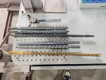
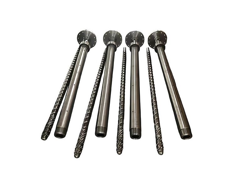
Workshop photograph of several plasticizing screws and a measuring tool for dimensional inspection. These are not a matched A B C set.
-
A Practical Selection Checklist for PIPLL Inquiries
- Identify the machine model, serial number and exact injection-unit size. Obtain the manufacturer's diameter options, L/D, shot volume, pressure and flow specifications.
- Record the total shot requirement on a consistent material or volume basis, plus the target cycle and available recovery time.
- Confirm the resin grade, glass or mineral filler, regrind content, drying needs and any optical or heat-sensitive requirements.
- Review filling-pressure demand, injection-flow demand, pressure-speed capability, cushion and recovery data. Use representative trials or validated analysis where available.
- Confirm component dimensions, screw geometry, check-valve configuration and wear-protection requirements before choosing the replacement assembly.
For injection screw barrel replacement, send the original drawing or measured dimensions and describe the reason for changing: pressure limitation, insufficient capacity, slow recovery, wear or discoloration.
-
Frequently Asked Questions
Does A always mean the best screw for engineering plastics?No. A may offer more pressure potential within a particular unit, but the resin can also require different geometry, temperature capability or material protection. Check the actual machine and grade specifications.Is B the safest choice when future jobs are unknown?It can be an intermediate compromise, but it cannot cover an undefined operating envelope. Compare likely minimum and maximum shots, materials, pressures and cycles before committing.Will C avoid buying a larger machine?Sometimes it can address a volume shortfall. It cannot resolve inadequate clamp force, pressure-speed capability, recovery performance or mold space. Verify all requirements together.Does a high L/D ratio guarantee better mixing?No. The effective length, channel design, compression section, mixing features and operating conditions must be considered together. More shear can also increase melt temperature or damage fibers. -
✔ Injection Screw & Barrel Specialist | ✔ A / B / C Diameter Selection Support
✔ Nitrided · Bimetallic · Through-Hardened | ✔ Custom Geometry · Wear Mapping · OEM Replacement