Extruder Screw Zones and How They Affect Processing
Unmelted particles appear in an extrudate. An injection molding machine takes longer to recover after back pressure increases. The barrel temperatures may look normal in both cases, yet the material can be experiencing very different conditions inside the screw.
Understanding extruder screw zones helps you connect the screw drawing with the feed, melting and pumping tasks. Start with three familiar sections on a conventional single screw, then compare the symptoms with actual melt temperature, output and load. PIPLL uses these application details when discussing screw geometry and replacement components. PIPLL single screw and barrel range .
Locate the Zones on the Screw Drawing
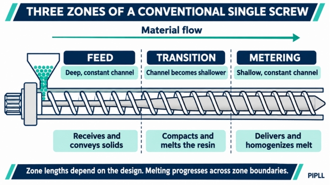
The feed section usually has a deep, approximately constant channel. The transition or compression section becomes shallower as the root diameter grows. The metering section generally has a shallow, approximately constant channel.
Figure 1. Channel depth identifies the feed, transition and metering sections on a conventional screw. Longitudinal schematic showing a deep feed channel, a shallowing transition channel and a shallow metering channel within a constant barrel bore.
These are geometric boundaries. Melting can begin in the feed section and continue into the metering section, depending on the resin and operating rate. The final section is best called the metering section, even when a shop floor description calls it the melting or homogenizing zone.
Follow the Material Through Each Section
Use the actual screw drawing to locate the boundaries. Heater bands and barrel control zones serve a different purpose and can span those boundaries. Barrier screws, vented screws and other special designs can have additional sections. Dynisco screw and barrel handbook .
Feed Section and Solids Conveying
Pellets enter through the feed throat and form a moving solids bed. In a conventional friction driven feed section, the balance between barrel and screw friction helps determine whether the bed advances. Feed form, bulk density, channel geometry and the smooth or grooved barrel design all influence intake.
If material bridges at the throat, inspect feed consistency, regrind shape and the throat cooling circuit. Look for softened or sticky pellets. Keep the throat at the machine and resin supplier's recommended condition. The first heated barrel zone still needs a suitable processing temperature, so a blanket instruction to keep the entire feed section cold can create another feeding or melting problem.
Transition Section and Melting
As the channel gets shallower, the solids bed compacts and the melt fraction grows. Barrel heat and mechanical energy both contribute. In the conventional melting model, a melt film and melt pool develop while the solid bed shrinks. Their location and progression change with material and geometry.
The geometric compression ratio compares feed channel capacity per turn with metering channel capacity per turn. For a conventional design with comparable pitch and channel width, the ratio is commonly approximated by feed channel depth divided by metering channel depth. A 6 mm feed depth and 2 mm metering depth illustrate a 3 to 1 ratio. This is a geometry example. Select the required ratio and transition length against the resin grade, output, torque and melt quality.
Crystallization behavior alone cannot set the transition length. PE film grades, nylon grades and PC grades have different melting, viscosity and stability requirements. A barrier design further changes how solids and melt move. Increasing compression to tackle an unmelt can also increase load or shear heating. Experimental study of LLDPE screw compression ratio .
Metering Section and Melt Delivery
The metering section aims to deliver a uniform melt at a steady rate against downstream resistance. Its depth and length influence pumping, pressure flow, shear and temperature. A conventional metering section can provide some homogenization, while a dedicated mixer may be needed for a particular color or additive requirement.
If unmelted fragments reach this section, review the melting capacity upstream as well as the metering conditions. A barrel setpoint alone cannot confirm complete melting. Measure actual melt temperature and examine samples at a stable production rate.
Use Symptoms to Choose the First Check
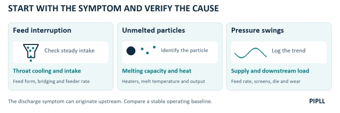
Feed interruption, unmelted particles and pressure swings with suggested initial checks.
Figure 2. The symptom identifies a starting check. Verify the cause against a stable operating baseline. Three initial checks link feed interruption to throat and intake checks, unmelted particles to melting capacity checks, and pressure swings to feed and downstream resistance checks.
Feed interruption or bridging. Check the hopper and feed throat, cooling flow, material condition and feeder stability. On an extruder, track output at constant rpm. On an injection unit, compare recovery consistency. A change in feed bulk density can affect both.
Unmelted particles. Confirm the particle is unmelted resin rather than contamination, filler or degraded residue. Check heaters, sensors, the grade's melt window and throughput relative to the screw's melting capacity. Compare melt temperature and particle incidence after one controlled adjustment. A symptom at the discharge can originate farther upstream.
High load or slow recovery. Identify whether the change followed a new resin, higher rate, higher injection back pressure or a different screen pack. For extrusion, compare head pressure and screen pressure drop where measured. For injection molding, review screw rpm, back pressure, melt temperature and recovery time together. Avient discusses these controls for plasticizing. Avient molding guidance .
Bubbles or splay. Verify drying where required, contamination, entrained air, degradation and the appropriate venting conditions. Compaction may allow some interstitial air to escape toward the hopper. Moisture and volatile removal can require drying or a purpose-designed vented system. In molded parts, also consider cavity venting and whether a void is caused by shrinkage. Eastman copolyester troubleshooting guide .
Pressure or color variation. Compare feed rate, melt temperature, rpm and downstream restriction before selecting a zone to modify. If the same recipe has gradually become less stable, inspect flight and bore wear at corresponding axial positions.
Match the Replacement Screw to the Actual Duty
For a screw barrel inspection report, map flight diameter, bore diameter and clearance along the screw rather than relying on one end measurement. Compare those readings with the drawing and the equipment supplier's limits. A worn pumping section and an inadequate melting section can require different remedies.
When discussing extruder screw zones with PIPLL, provide the resin grade, filler and regrind content, target kg/h, motor and gearbox information, and the existing drawing. Include feed, transition and metering lengths, channel depths and any mixer or barrier features. PIPLL's customization process uses machine dimensions and operating requirements to review the proposed geometry. PIPLL custom screw and barrel service .
For example, a blown film application needs the screw assessed alongside the blend, die resistance, melt quality and cooling limit. Share that operating window when reviewing a product option. PIPLL film blowing screw and barrel .
Confirm drawing dimensions, metallurgy and the agreed inspection records before ordering. These details support a screw barrel acceptance inspection checklist and help the replacement match the intended duty. PIPLL manufacturing process .
Frequently Asked Questions
Do the three sections have fixed percentages? Their lengths depend on the design and application. Mark the boundaries from channel geometry on the drawing.
Is the metering section the same as the last heater zone? Heater zone locations and screw section boundaries can differ. In an injection unit, the screw also moves axially through the cycle.
Can I use this model for injection molding? It helps explain plasticizing during screw recovery. The following injection stroke uses the screw as a plunger, with the check valve controlling backflow. Evaluate recovery separately from mold filling.
Send PIPLL the Drawing and the Operating Baseline
Send the machine model, resin grade, screw drawing, output or shot weight, rpm, actual melt temperature and the defect history. For an injection machine, add back pressure and recovery time. PIPLL can use that information to discuss which geometry or wear measurements to review next. Contact PIPLL .
Technical and Sales Contact
Harry Jiang | PIPLL
Email: harry@pipll.com | WhatsApp: +86 182 6854 1152
Website: www.pipll.com


+86 15267878906

1306 W building , NB-IoT Industrial Park, No. 199 Changxing Road, Jiangbei, Ningbo.
 Languages